8. Operation
8.10 The Smart Move* Control Panel
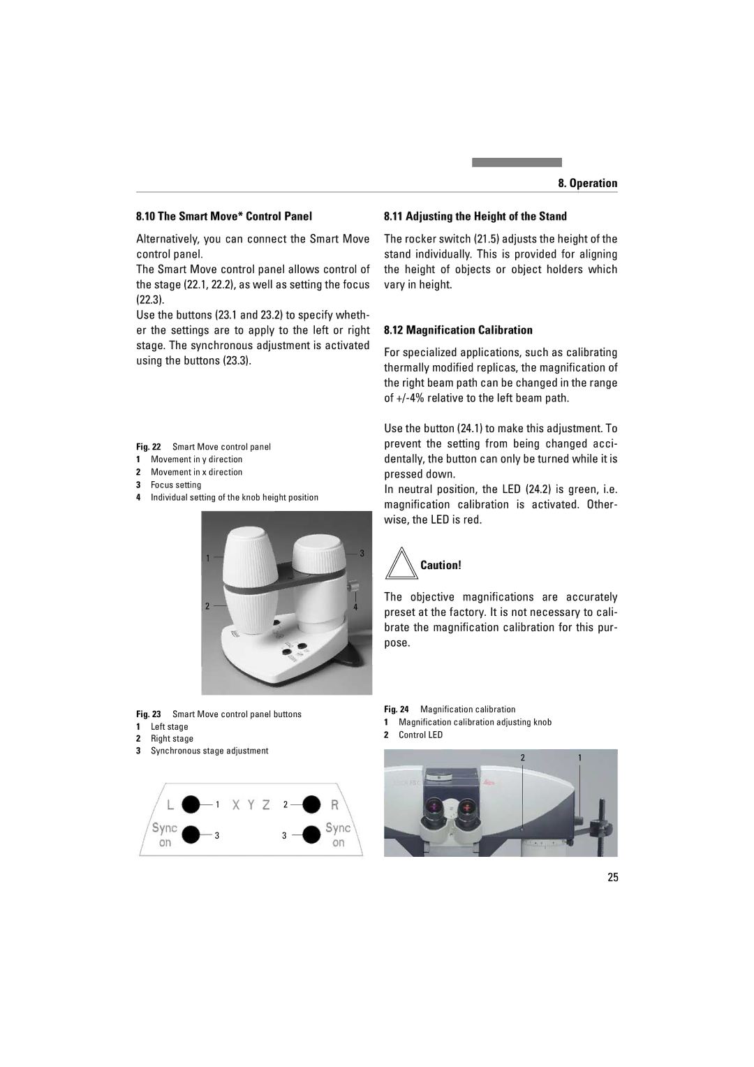
Alternatively, you can connect the Smart Move control panel.
The Smart Move control panel allows control of the stage (22.1, 22.2), as well as setting the focus (22.3).
Use the buttons (23.1 and 23.2) to specify wheth- er the settings are to apply to the left or right stage. The synchronous adjustment is activated using the buttons (23.3).
8.11 Adjusting the Height of the Stand
The rocker switch (21.5) adjusts the height of the stand individually. This is provided for aligning the height of objects or object holders which vary in height.
8.12 Magnification Calibration
For specialized applications, such as calibrating thermally modified replicas, the magnification of the right beam path can be changed in the range of
Fig. 22 Smart Move control panel
1Movement in y direction
2Movement in x direction
3Focus setting
4Individual setting of the knob height position
1
2
3
4
Use the button (24.1) to make this adjustment. To prevent the setting from being changed acci- dentally, the button can only be turned while it is pressed down.
In neutral position, the LED (24.2) is green, i.e. magnification calibration is activated. Other- wise, the LED is red.
Caution!
The objective magnifications are accurately preset at the factory. It is not necessary to cali- brate the magnification calibration for this pur- pose.
Fig. 23 Smart Move control panel buttons
1Left stage
2Right stage
3Synchronous stage adjustment
12
33
Fig. 24 Magnification calibration
1Magnification calibration adjusting knob
2Control LED
21
25