8. Operation
8.2 Stages
The stages on the left and right side can be moved either independently of each other, or simultaneously in the X and Y directions.
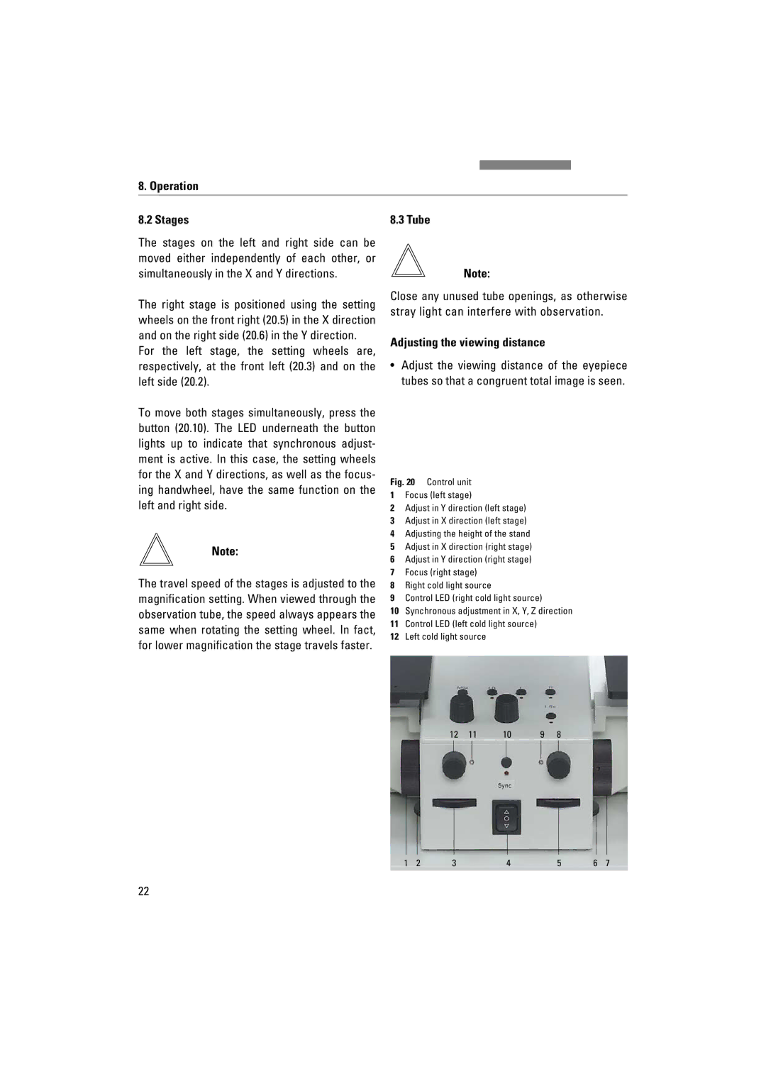
The right stage is positioned using the setting wheels on the front right (20.5) in the X direction and on the right side (20.6) in the Y direction.
For the left stage, the setting wheels are, respectively, at the front left (20.3) and on the left side (20.2).
To move both stages simultaneously, press the button (20.10). The LED underneath the button lights up to indicate that synchronous adjust- ment is active. In this case, the setting wheels for the X and Y directions, as well as the focus- ing handwheel, have the same function on the left and right side.
Note:
The travel speed of the stages is adjusted to the magnification setting. When viewed through the observation tube, the speed always appears the same when rotating the setting wheel. In fact, for lower magnification the stage travels faster.
8.3 Tube
Note:
Close any unused tube openings, as otherwise stray light can interfere with observation.
Adjusting the viewing distance
•Adjust the viewing distance of the eyepiece tubes so that a congruent total image is seen.
Fig. 20 Control unit
1Focus (left stage)
2Adjust in Y direction (left stage)
3Adjust in X direction (left stage)
4Adjusting the height of the stand
5Adjust in X direction (right stage)
6Adjust in Y direction (right stage)
7Focus (right stage)
8Right cold light source
9Control LED (right cold light source)
10Synchronous adjustment in X, Y, Z direction
11Control LED (left cold light source)
12Left cold light source
12 | 11 | 10 | 9 | 8 |
1 | 2 | 3 | 4 | 5 | 6 | 7 |
22