1 − When the thermostat is set to AN ON," the indoor blower will run continuously at a percentage of the sec- ond−stage cooling speed when there is no cooling or heating demand. The percentage is set using DIP switches 6 and 7.
2 − When the SLP98DFV is running in the heating mode, the integrated control will automatically adjust the blower speed to match the furnace firing rate. This speed can be adjusted up or down by 7.5% or 15% us- ing DIP switches 14 through 16 for the low heat speed and 17 through 19 for the high heat speed.
3 − When there is a cooling demand, the indoor blower will run on the cooling speed designated by the positions of DIP switches 8 through 11.
Generator Use − Voltage Requirements
The following requirements must be kept in mind when specifying a generator for use with this equipment:
D The furnace requires 120 volts + 10% (Range: 108 volts to 132 volts).
DThe furnace operates at 60 Hz + 5% (Range: 57 Hz to 63 Hz).
DThe furnace integrated control requires both polarity and proper ground. Both polarity and proper grounding should be checked before attempting to operate the furnace on either permanent or temporary power.
DGenerator should have a wave form distortion of less than 5% THD (total harmonic distortion).
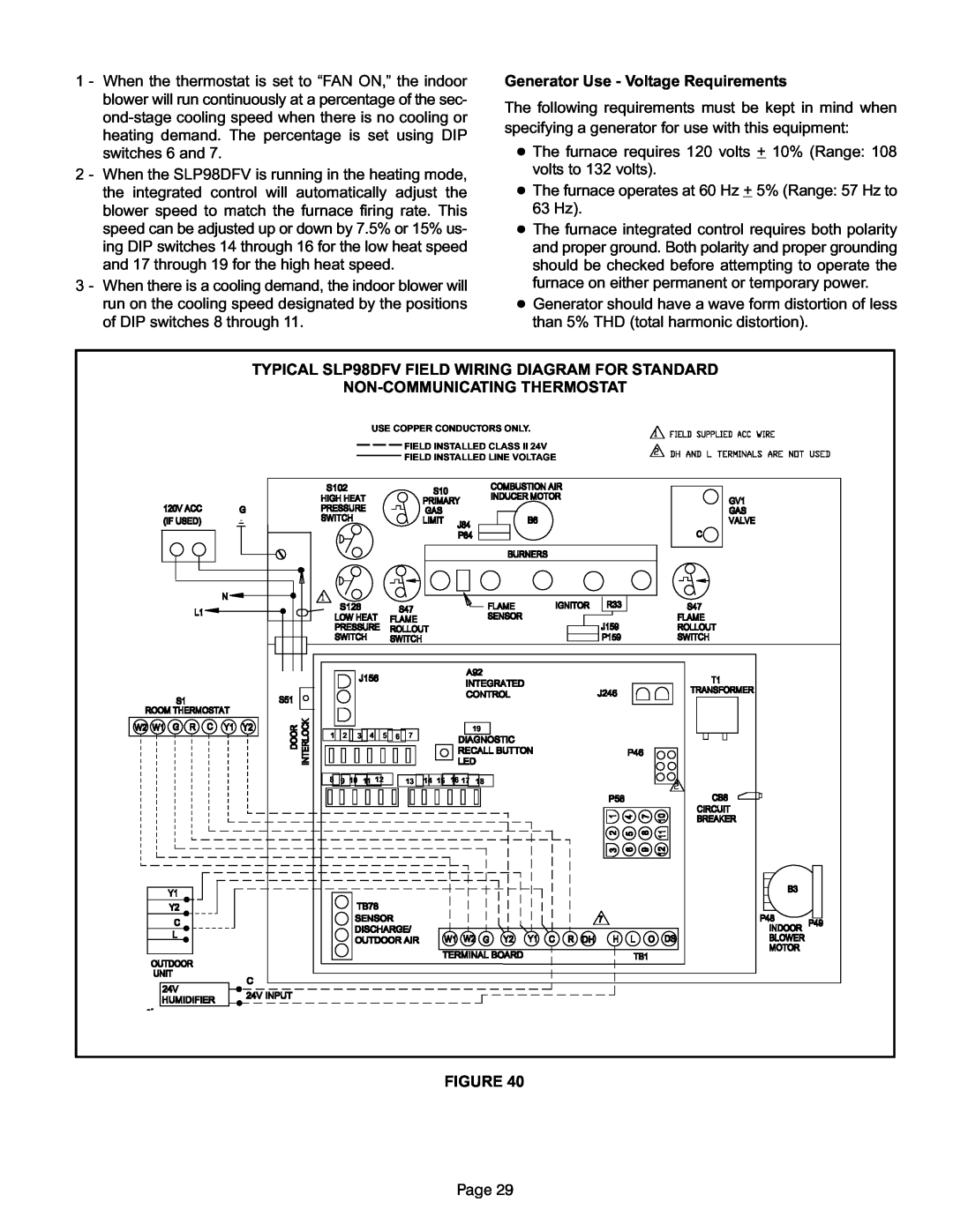
TYPICAL SLP98DFV FIELD WIRING DIAGRAM FOR STANDARD
NON−COMMUNICATING THERMOSTAT
USE COPPER CONDUCTORS ONLY.
FIELD INSTALLED CLASS II 24V
FIELD INSTALLED LINE VOLTAGE
1![]()
![]() 2
2 ![]()
![]() 3
3![]()
![]() 4
4 ![]()
![]() 5
5![]()
![]() 6
6 ![]()
![]() 7
7
19
8![]()
![]() 9 10 11 12
9 10 11 12
13 ![]()
![]() 14 15 16 17 18
14 15 16 17 18
FIGURE 40
Page 29