MANUAL
MAIN SHUT−OFF
VALVE
(1/8 in. NPT
plugged tap shown)
GROUND
JOINT
UNION
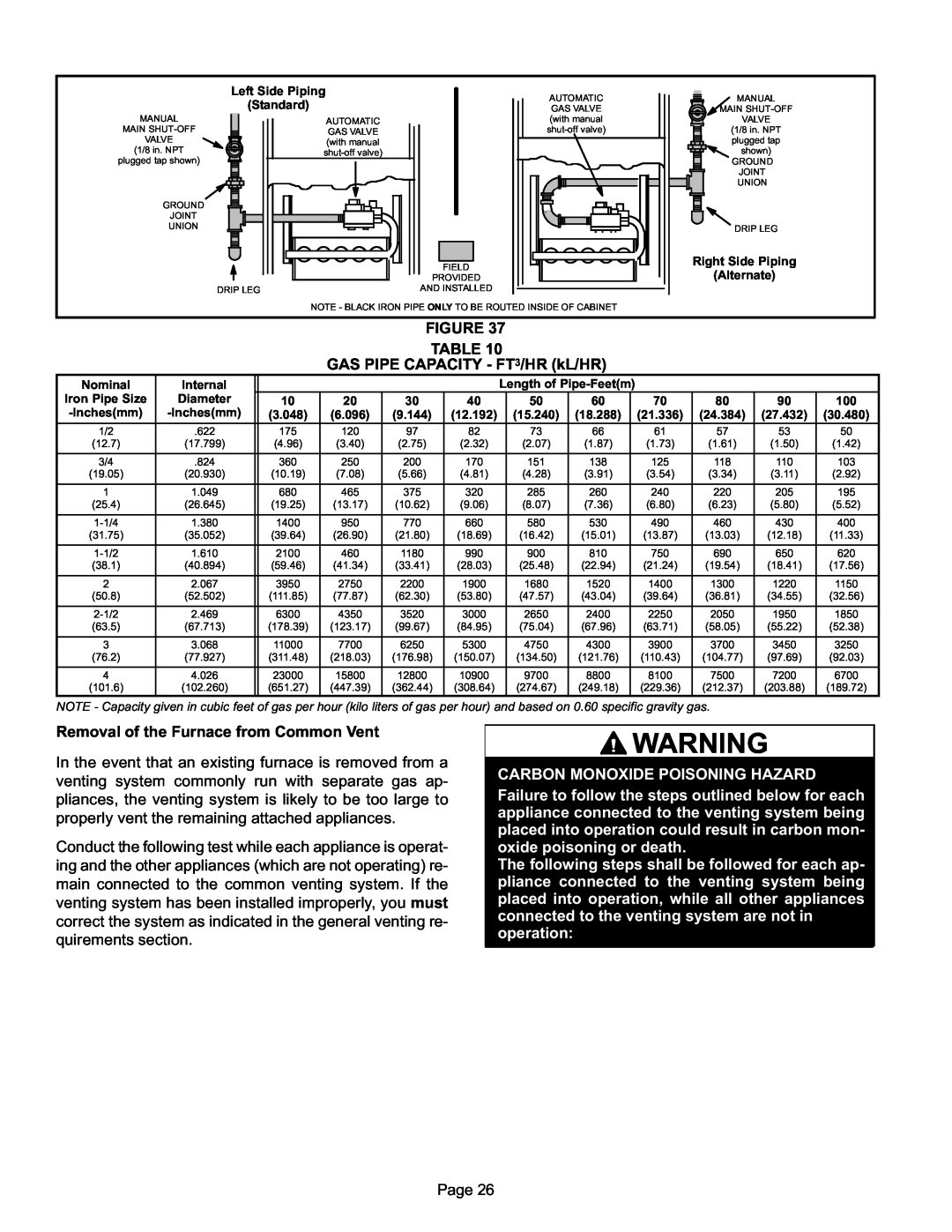
Left Side Piping
(Standard)
AUTOMATIC |
GAS VALVE |
(with manual |
shut−off valve) |
FIELD
PROVIDED
AUTOMATIC |
GAS VALVE |
(with manual |
shut−off valve) |
MANUAL
MAIN SHUT−OFF
VALVE
(1/8 in. NPT
plugged tap
shown)
GROUND
JOINT UNION
DRIP LEG
Right Side Piping
(Alternate)
DRIP LEG
AND INSTALLED
NOTE − BLACK IRON PIPE ONLY TO BE ROUTED INSIDE OF CABINET
FIGURE 37
TABLE 10
GAS PIPE CAPACITY − FT3/HR (kL/HR)
Nominal
Iron Pipe Size
−Inches(mm)
Internal
Diameter
−Inches(mm)
Length of Pipe−Feet(m)
10 | 20 | 30 | 40 | 50 | 60 | 70 | 80 | 90 | 100 |
(3.048) | (6.096) | (9.144) | (12.192) | (15.240) | (18.288) | (21.336) | (24.384) | (27.432) | (30.480) |
1/2 | .622 | 175 | 120 | 97 | 82 | 73 | 66 | 61 | 57 | 53 | 50 |
(12.7) | (17.799) | (4.96) | (3.40) | (2.75) | (2.32) | (2.07) | (1.87) | (1.73) | (1.61) | (1.50) | (1.42) |
|
|
|
|
|
|
|
|
|
|
|
|
3/4 | .824 | 360 | 250 | 200 | 170 | 151 | 138 | 125 | 118 | 110 | 103 |
(19.05) | (20.930) | (10.19) | (7.08) | (5.66) | (4.81) | (4.28) | (3.91) | (3.54) | (3.34) | (3.11) | (2.92) |
|
|
|
|
|
|
|
|
|
|
|
|
1 | 1.049 | 680 | 465 | 375 | 320 | 285 | 260 | 240 | 220 | 205 | 195 |
(25.4) | (26.645) | (19.25) | (13.17) | (10.62) | (9.06) | (8.07) | (7.36) | (6.80) | (6.23) | (5.80) | (5.52) |
|
|
|
|
|
|
|
|
|
|
|
|
1−1/4 | 1.380 | 1400 | 950 | 770 | 660 | 580 | 530 | 490 | 460 | 430 | 400 |
(31.75) | (35.052) | (39.64) | (26.90) | (21.80) | (18.69) | (16.42) | (15.01) | (13.87) | (13.03) | (12.18) | (11.33) |
|
|
|
|
|
|
|
|
|
|
|
|
1−1/2 | 1.610 | 2100 | 460 | 1180 | 990 | 900 | 810 | 750 | 690 | 650 | 620 |
(38.1) | (40.894) | (59.46) | (41.34) | (33.41) | (28.03) | (25.48) | (22.94) | (21.24) | (19.54) | (18.41) | (17.56) |
|
|
|
|
|
|
|
|
|
|
|
|
2 | 2.067 | 3950 | 2750 | 2200 | 1900 | 1680 | 1520 | 1400 | 1300 | 1220 | 1150 |
(50.8) | (52.502) | (111.85) | (77.87) | (62.30) | (53.80) | (47.57) | (43.04) | (39.64) | (36.81) | (34.55) | (32.56) |
|
|
|
|
|
|
|
|
|
|
|
|
2−1/2 | 2.469 | 6300 | 4350 | 3520 | 3000 | 2650 | 2400 | 2250 | 2050 | 1950 | 1850 |
(63.5) | (67.713) | (178.39) | (123.17) | (99.67) | (84.95) | (75.04) | (67.96) | (63.71) | (58.05) | (55.22) | (52.38) |
|
|
|
|
|
|
|
|
|
|
|
|
3 | 3.068 | 11000 | 7700 | 6250 | 5300 | 4750 | 4300 | 3900 | 3700 | 3450 | 3250 |
(76.2) | (77.927) | (311.48) | (218.03) | (176.98) | (150.07) | (134.50) | (121.76) | (110.43) | (104.77) | (97.69) | (92.03) |
|
|
|
|
|
|
|
|
|
|
|
|
4 | 4.026 | 23000 | 15800 | 12800 | 10900 | 9700 | 8800 | 8100 | 7500 | 7200 | 6700 |
(101.6) | (102.260) | (651.27) | (447.39) | (362.44) | (308.64) | (274.67) | (249.18) | (229.36) | (212.37) | (203.88) | (189.72) |
|
|
|
|
|
|
|
|
|
|
|
|
NOTE − Capacity given in cubic feet of gas per hour (kilo liters of gas per hour) and based on 0.60 specific gravity gas.
Removal of the Furnace from Common Vent
In the event that an existing furnace is removed from a venting system commonly run with separate gas ap- pliances, the venting system is likely to be too large to properly vent the remaining attached appliances.
Conduct the following test while each appliance is operat- ing and the other appliances (which are not operating) re- main connected to the common venting system. If the venting system has been installed improperly, you must correct the system as indicated in the general venting re- quirements section.
![]() WARNING
WARNING
CARBON MONOXIDE POISONING HAZARD
Failure to follow the steps outlined below for each appliance connected to the venting system being placed into operation could result in carbon mon- oxide poisoning or death.
The following steps shall be followed for each ap- pliance connected to the venting system being placed into operation, while all other appliances connected to the venting system are not in operation:
Page 26