Unit Start−Up
FOR YOUR SAFETY READ BEFORE OPERATING
![]() WARNING
WARNING
Do not use this furnace if any part has been under- water. A flood−damaged furnace is extremely dan- gerous. Attempts to use the furnace can result in fire or explosion. Immediately call a qualified ser- vice technician to inspect the furnace and to replace all gas controls, control system parts, and electrical parts that have been wet or to replace the furnace, if deemed necessary.
![]() WARNING
WARNING
Danger of explosion. Can cause injury or product or property damage. Should the gas supply fail to shut off or if overheating occurs, shut off the gas valve to the furnace before shutting off the electrical supply.
![]() CAUTION
CAUTION
Before attempting to perform any service or mainte- nance, turn the electrical power to unit OFF at dis- connect switch.
![]() WARNING
WARNING
During blower operation, the ECM motor emits ener- gy that may interfere with pacemaker operation. In- terference is reduced by both the sheet metal cabinet and distance.
Priming Condensate Trap
The condensate trap should be primed with water prior to start−up to ensure proper condensate drainage. Either pour 10 fl. oz. (300 ml) of water into the trap, or follow these steps to prime the trap:
1 − Follow the lighting instructions to place the unit into op- eration.
2 − Set the thermostat to initiate a heating demand.
3 − Allow the burners to fire for approximately 3 minutes.
4 − Adjust the thermostat to deactivate the heating de- mand.
5 − Wait for the combustion air inducer to stop. Set the thermostat to initiate a heating demand and again al- low the burners to fire for approximately 3 minutes.
6 − Adjust the thermostat to deactivate the heating de- mand and again wait for the combustion air inducer to stop. At this point, the trap should be primed with suffi- cient water to ensure proper condensate drain opera- tion.
BEFORE BEFORE PLACING THE UNIT INTO OPERA- TION, smell all around the furnace area for gas. Be sure to smell next to the floor because some gas is heavier than air and will settle on the floor.
The gas valve on the SLP98DFV is equipped with a gas control switch. Use only your hand to move the control switch. Never use tools. If the switch will not move by hand, do not try to repair it. Force or attempted repair may result in a fire or explosion.
Placing the furnace into operation:
SLP98DFV units are equipped with an automatic ignition system. Do not attempt to manually light burners on this furnace. Each time the thermostat calls for heat, the burners will automatically light. The ignitor does not get hot when there is no call for heat on units with this ignition system.
![]() WARNING
WARNING
If you do not follow these instructions exactly, a fire or explosion may result causing property damage, personal injury or death.
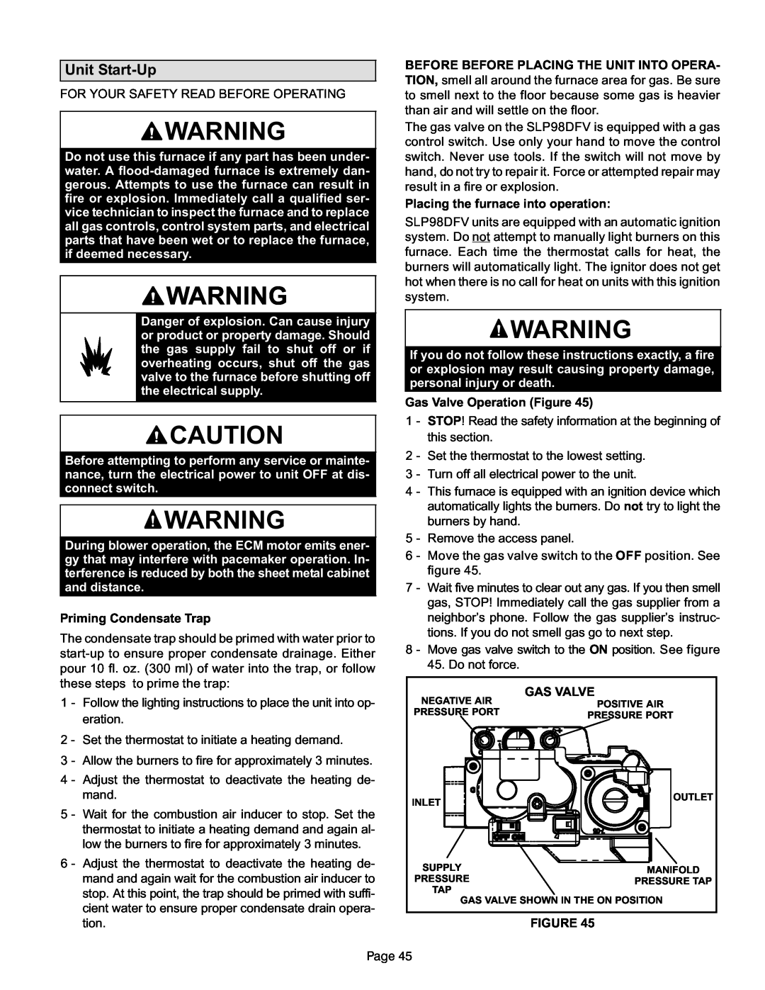
Gas Valve Operation (Figure 45)
1 − STOP! Read the safety information at the beginning of this section.
2 − Set the thermostat to the lowest setting.
3 − Turn off all electrical power to the unit.
4 − This furnace is equipped with an ignition device which automatically lights the burners. Do not try to light the burners by hand.
5 − Remove the access panel.
6 − Move the gas valve switch to the OFF position. See figure 45.
7 − Wait five minutes to clear out any gas. If you then smell gas, STOP! Immediately call the gas supplier from a neighbor’s phone. Follow the gas supplier’s instruc- tions. If you do not smell gas go to next step.
8 − Move gas valve switch to the ON position. See figure 45. Do not force.
NEGATIVE AIR | GAS VALVE | |
POSITIVE AIR | ||
PRESSURE PORT | ||
PRESSURE PORT | ||
| ||
INLET | OUTLET | |
| ||
SUPPLY | MANIFOLD | |
PRESSURE | ||
PRESSURE TAP | ||
TAP | ||
| ||
GAS VALVE SHOWN IN THE ON POSITION | ||
FIGURE 45
Page 45