Integrated Control Diagnostic Codes
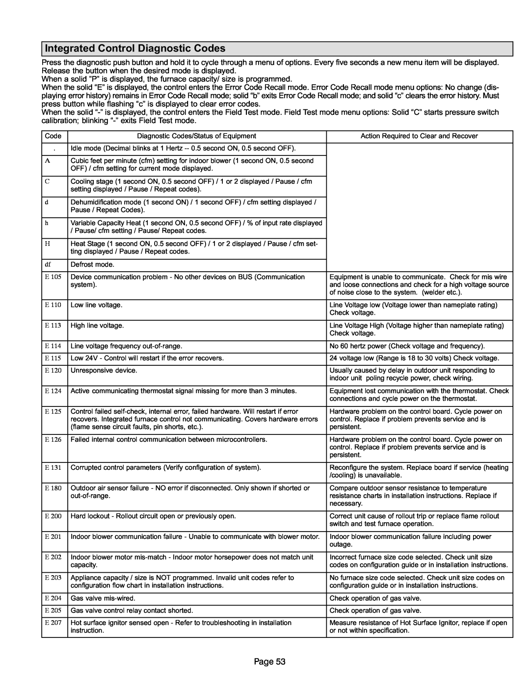
Press the diagnostic push button and hold it to cycle through a menu of options. Every five seconds a new menu item will be displayed. Release the button when the desired mode is displayed.
When a solid "P" is displayed, the furnace capacity/ size is programmed. |
|
|
| ||
When the solid |
| Error Code Recall mode menu options: No change (dis- | |||
playing error history) remains in Error Code Recall mode; solid s Error Code Recall mode; and solid | y. Must | ||||
press button while flashing |
|
|
|
| |
When the solid | the Field Test mode. Field Test mode menu options: Solid arts pressur | e switch | |||
calibration; blinking s Field Test mode. |
|
|
| ||
|
|
|
|
| |
Code |
| Diagnostic Codes/Status of Equipment |
| Action Required to Clear and Recover | |
|
|
|
|
| |
. | Idle mode (Decimal blinks at 1 Hertz −− 0.5 second ON, 0.5 second OFF). |
|
|
| |
|
|
|
|
|
|
ACubic feet per minute (cfm) setting for indoor blower (1 second ON, 0.5 second OFF) / cfm setting for current mode displayed.
C
Cooling stage (1 second ON, 0.5 second OFF) / 1 or 2 displayed / Pause / cfm setting displayed / Pause / Repeat codes).
d
Dehumidification mode (1 second ON) / 1 second OFF) / cfm setting displayed / Pause / Repeat Codes).
h
Variable Capacity Heat (1 second ON, 0.5 second OFF) / % of input rate displayed / Pause/ cfm setting / Pause/ Repeat codes.
H
Heat Stage (1 second ON, 0.5 second OFF) / 1 or 2 displayed / Pause / cfm set- ting displayed / Pause / Repeat codes.
df | Defrost mode. |
|
|
|
|
E 105 | Device communication problem − No other devices on BUS (Communication | Equipment is unable to communicate. Check for mis wire |
| system). | and loose connections and check for a high voltage source |
|
| of noise close to the system. (welder etc.). |
|
|
|
E 110 | Low line voltage. | Line Voltage low (Voltage lower than nameplate rating) |
|
| Check voltage. |
|
|
|
E 113 | High line voltage. | Line Voltage High (Voltage higher than nameplate rating) |
|
| Check voltage. |
|
|
|
E 114 | Line voltage frequency out−of−range. | No 60 hertz power (Check voltage and frequency). |
|
|
|
E 115 | Low 24V − Control will restart if the error recovers. | 24 voltage low (Range is 18 to 30 volts) Check voltage. |
|
|
|
E 120 | Unresponsive device. | Usually caused by delay in outdoor unit responding to |
|
| indoor unit poling recycle power, check wiring. |
|
|
|
E 124 | Active communicating thermostat signal missing for more than 3 minutes. | Equipment lost communication with the thermostat. Check |
|
| connections and cycle power on the thermostat. |
|
|
|
E 125 | Control failed self−check, internal error, failed hardware. Will restart if error | Hardware problem on the control board. Cycle power on |
| recovers. Integrated furnace control not communicating. Covers hardware errors | control. Replace if problem prevents service and is |
| (flame sense circuit faults, pin shorts, etc.). | persistent. |
|
|
|
E 126 | Failed internal control communication between microcontrollers. | Hardware problem on the control board. Cycle power on |
|
| control. Replace if problem prevents service and is |
|
| persistent. |
|
|
|
E 131
Corrupted control parameters (Verify configuration of system).
Reconfigure the system. Replace board if service (heating /cooling) is unavailable.
E 180
Outdoor air sensor failure − NO error if disconnected. Only shown if shorted or out−of−range.
Compare outdoor sensor resistance to temperature resistance charts in installation instructions. Replace if necessary.
E 200 | Hard lockout − Rollout circuit open or previously open. | Correct unit cause of rollout trip or replace flame rollout |
|
| switch and test furnace operation. |
|
|
|
E 201 | Indoor blower communication failure − Unable to communicate with blower motor. | Indoor blower communication failure including power |
|
| outage. |
|
|
|
E 202 | Indoor blower motor mis−match − Indoor motor horsepower does not match unit | Incorrect furnace size code selected. Check unit size |
| capacity. | codes on configuration guide or in installation instructions. |
|
|
|
E 203 | Appliance capacity / size is NOT programmed. Invalid unit codes refer to | No furnace size code selected. Check unit size codes on |
| configuration flow chart in installation instructions. | configuration guide or in installation instructions. |
|
|
|
E 204 | Gas valve mis−wired. | Check operation of gas valve. |
|
|
|
E 205 | Gas valve control relay contact shorted. | Check operation of gas valve. |
|
|
|
E 207 | Hot surface ignitor sensed open − Refer to troubleshooting in installation | Measure resistance of Hot Surface Ignitor, replace if open |
| instruction. | or not within specification. |
|
|
|
Page 53