TABLE 1
NON−COMBUSTIBLE FLOOR OPENING SIZE
| Front to Rear | Side to Side | |||
Cabinet Width |
|
|
|
| |
in. | mm | in. | mm | ||
| |||||
|
|
|
|
| |
B Cabinet (17.5") | 19 − 3/4 | 502 | 16 − 5/8 | 422 | |
|
|
|
|
| |
C Cabinet (21") | 19 − 3/4 | 502 | 20−1/8 | 511 | |
|
|
|
|
| |
NOTE − Floor opening dimensions listed are 1/4 inch (6 mm) larger than the unit opening. See dimension drawing on page 2.
SLP98DF UNIT
SLP98DF UNIT
PROPERLY SIZED FLOOR OPENING
SUPPLY AIR
PLENUM
COMBUSTIBLE FLOORING BASE
PROPERLY |
|
SIZED FLOOR | SUPPLY AIR |
OPENING | PLENUM |
FIGURE 8
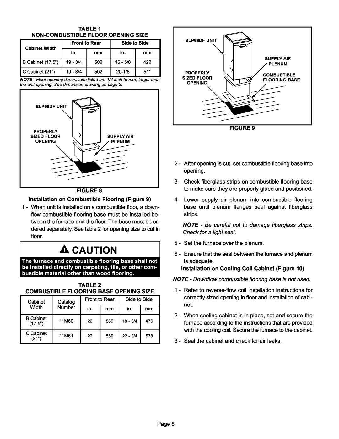
Installation on Combustible Flooring (Figure 9)
1 − When unit is installed on a combustible floor, a down- flow combustible flooring base must be installed be- tween the furnace and the floor. The base must be or- dered separately. See table 2 for opening size to cut in floor.
![]() CAUTION
CAUTION
The furnace and combustible flooring base shall not be installed directly on carpeting, tile, or other com- bustible material other than wood flooring.
TABLE 2
COMBUSTIBLE FLOORING BASE OPENING SIZE
Cabinet | Catalog | Front to Rear | Side to Side | |||
|
|
|
| |||
Width | Number | in. | mm | in. | mm | |
|
| |||||
|
|
|
|
|
| |
B Cabinet | 11M60 | 22 | 559 | 18 − 3/4 | 476 | |
(17.5") | ||||||
|
|
|
|
| ||
|
|
|
|
|
| |
C Cabinet | 11M61 | 22 | 559 | 22 − 3/4 | 578 | |
(21") | ||||||
|
|
|
|
| ||
|
|
|
|
|
| |
FIGURE 9
2 − After opening is cut, set combustible flooring base into opening.
3 − Check fiberglass strips on combustible flooring base to make sure they are properly glued and positioned.
4 − Lower supply air plenum into combustible flooring base until plenum flanges seal against fiberglass strips.
NOTE − Be careful not to damage fiberglass strips. Check for a tight seal.
5 − Set the furnace over the plenum.
6 − Ensure that the seal between the furnace and plenum is adequate.
Installation on Cooling Coil Cabinet (Figure 10)
NOTE − Downflow combustible flooring base is not used.
1 − Refer to reverse−flow coil installation instructions for correctly sized opening in floor and installation of cabi- net.
2 − When cooling cabinet is in place, set and secure the furnace according to the instructions that are provided with the cooling coil. Secure the furnace to the cabinet.
3 − Seal the cabinet and check for air leaks.
Page 8