BLOWER DATA
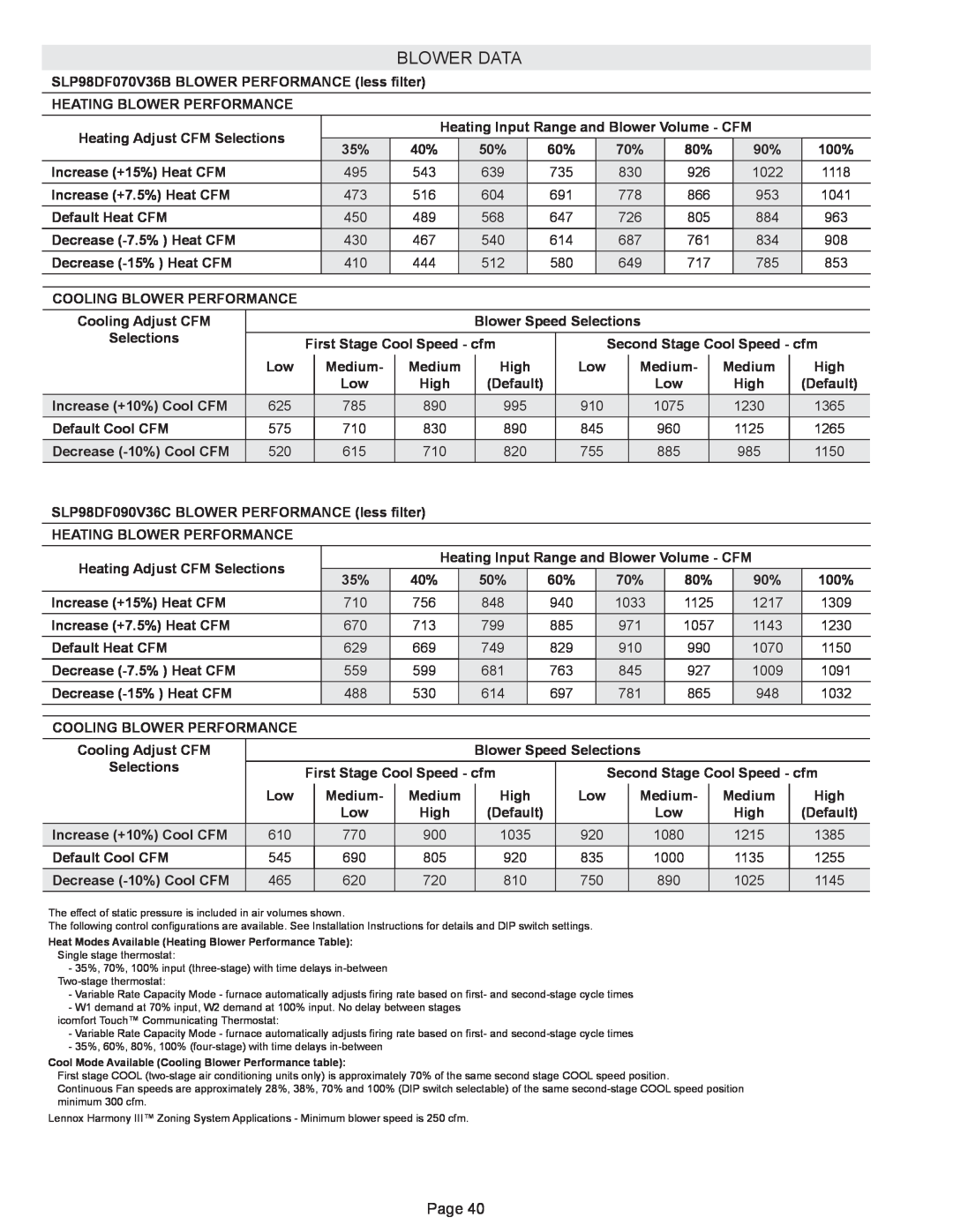
SLP98DF070V36B BLOWER PERFORMANCE (less filter)
HEATING BLOWER PERFORMANCE
Heating Adjust CFM Selections |
|
|
|
| Heating Input Range and Blower Volume - CFM |
|
| |||||||||||||||
|
| 35% | 40% |
| 50% |
| 60% |
| 70% |
| 80% |
| 90% |
| 100% | |||||||
|
|
|
|
|
|
|
|
|
| |||||||||||||
Increase (+15%) Heat CFM |
|
|
| 495 | 543 |
| 639 |
| 735 |
| 830 |
| 926 |
| 1022 |
| 1118 | |||||
Increase (+7.5%) Heat CFM |
|
|
| 473 | 516 |
| 604 |
| 691 |
| 778 |
| 866 |
| 953 |
| 1041 | |||||
Default Heat CFM |
|
|
| 450 | 489 |
| 568 |
| 647 |
| 726 |
| 805 |
| 884 |
| 963 | |||||
Decrease |
|
|
| 430 | 467 |
| 540 |
| 614 |
| 687 |
| 761 |
| 834 |
| 908 | |||||
Decrease |
|
|
| 410 | 444 |
| 512 |
| 580 |
| 649 |
| 717 |
| 785 |
| 853 | |||||
|
|
|
|
|
|
|
|
|
|
|
|
|
|
|
|
|
|
|
|
|
|
|
COOLING BLOWER PERFORMANCE |
|
|
|
|
|
|
|
|
|
|
|
|
|
|
|
|
|
|
|
|
| |
Cooling Adjust CFM |
|
|
|
|
|
|
| Blower Speed Selections |
|
|
|
|
|
|
| |||||||
Selections |
| First Stage Cool Speed - cfm |
|
|
| Second Stage Cool Speed - cfm | ||||||||||||||||
|
|
|
|
| ||||||||||||||||||
| Low |
|
| Medium- |
| Medium |
| High |
| Low |
| Medium- |
| Medium |
| High | ||||||
|
|
|
| Low |
| High |
| (Default) |
|
|
|
|
| Low |
|
| High | (Default) | ||||
Increase (+10%) Cool CFM | 625 |
| 785 |
| 890 |
|
| 995 |
|
| 910 |
|
| 1075 |
| 1230 | 1365 | |||||
Default Cool CFM | 575 |
| 710 |
| 830 |
|
| 890 |
|
| 845 |
|
| 960 |
| 1125 | 1265 | |||||
Decrease | 520 |
| 615 |
| 710 |
|
| 820 |
|
| 755 |
|
| 885 |
| 985 | 1150 | |||||
SLP98DF090V36C BLOWER PERFORMANCE (less filter) |
|
|
|
|
|
|
|
|
|
|
|
|
|
|
| |||||||
HEATING BLOWER PERFORMANCE |
|
|
|
|
|
|
|
|
|
|
|
|
|
|
|
|
|
|
|
|
| |
Heating Adjust CFM Selections |
|
|
|
| Heating Input Range and Blower Volume - CFM |
|
| |||||||||||||||
|
| 35% | 40% |
| 50% |
| 60% |
| 70% |
| 80% |
| 90% |
| 100% | |||||||
|
|
|
|
|
|
|
|
| ||||||||||||||
Increase (+15%) Heat CFM |
|
|
| 710 | 756 |
| 848 |
| 940 |
| 1033 |
| 1125 |
| 1217 |
| 1309 | |||||
Increase (+7.5%) Heat CFM |
|
|
| 670 | 713 |
| 799 |
| 885 |
| 971 |
| 1057 |
| 1143 |
| 1230 | |||||
Default Heat CFM |
|
|
| 629 | 669 |
| 749 |
| 829 |
| 910 |
| 990 |
| 1070 |
| 1150 | |||||
Decrease |
|
|
| 559 | 599 |
| 681 |
| 763 |
| 845 |
| 927 |
| 1009 |
| 1091 | |||||
Decrease |
|
|
| 488 | 530 |
| 614 |
| 697 |
| 781 |
| 865 |
| 948 |
| 1032 | |||||
|
|
|
|
|
|
|
|
|
|
|
|
|
|
|
|
|
|
|
|
|
| |
COOLING BLOWER PERFORMANCE |
|
|
|
|
|
|
|
|
|
|
|
|
|
|
|
|
|
|
|
|
| |
Cooling Adjust CFM |
|
|
|
|
|
|
| Blower Speed Selections |
|
|
|
|
|
|
| |||||||
Selections |
|
|
|
|
|
|
|
|
|
|
|
|
|
|
|
|
|
|
|
|
|
|
| First Stage Cool Speed - cfm |
|
|
| Second Stage Cool Speed - cfm | |||||||||||||||||
|
|
|
|
| ||||||||||||||||||
| Low |
|
| Medium- |
| Medium |
| High |
| Low |
| Medium- |
| Medium |
| High | ||||||
|
|
|
| Low |
| High |
| (Default) |
|
|
|
|
| Low |
|
| High | (Default) | ||||
Increase (+10%) Cool CFM | 610 |
| 770 |
| 900 |
|
| 1035 |
| 920 |
|
| 1080 |
| 1215 | 1385 | ||||||
Default Cool CFM | 545 |
| 690 |
| 805 |
|
| 920 |
|
| 835 |
|
| 1000 |
| 1135 | 1255 | |||||
Decrease | 465 |
| 620 |
| 720 |
|
| 810 |
|
| 750 |
|
| 890 |
| 1025 | 1145 | |||||
The effect of static pressure is included in air volumes shown.
The following control configurations are available. See Installation Instructions for details and DIP switch settings.
Heat Modes Available (Heating Blower Performance Table):
Single stage thermostat:
-35%, 70%, 100% input
-Variable Rate Capacity Mode - furnace automatically adjusts firing rate based on first- and
-W1 demand at 70% input, W2 demand at 100% input. No delay between stages
icomfort Touch™ Communicating Thermostat:
-Variable Rate Capacity Mode - furnace automatically adjusts firing rate based on first- and
-35%, 60%, 80%, 100%
Cool Mode Available (Cooling Blower Performance table):
First stage COOL
Continuous Fan speeds are approximately 28%, 38%, 70% and 100% (DIP switch selectable) of the same
Lennox Harmony III™ Zoning System Applications - Minimum blower speed is 250 cfm.
Page 40