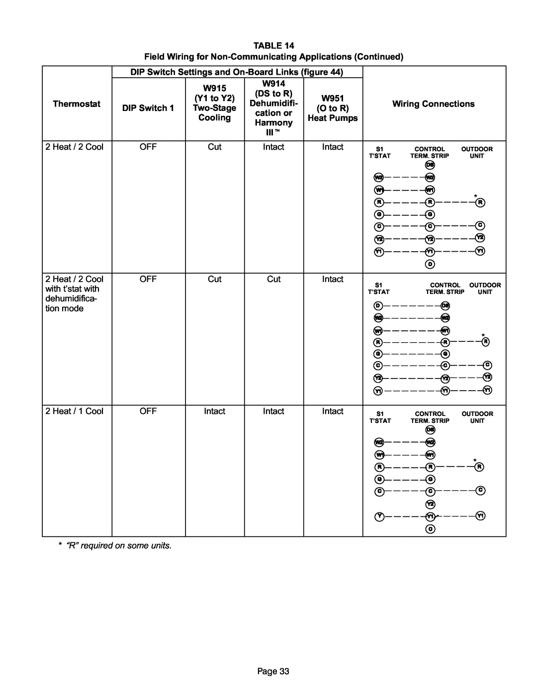
TABLE 14
Field Wiring for Non−Communicating Applications (Continued)
Thermostat
DIP Switch Settings and On−Board Links (figure 44)
| W915 | W914 |
| |
| (DS to R) |
| ||
| (Y1 to Y2) | W951 | ||
| Dehumidifi- | |||
DIP Switch 1 | Two−Stage | (O to R) | ||
cation or | ||||
| Cooling | Heat Pumps | ||
| Harmony | |||
|
|
| ||
|
| IIIt |
| |
|
|
|
|
Wiring Connections
2 Heat / 2 Cool
OFF
Cut
Intact
Intact
S1 | CONTROL | OUTDOOR |
T’STAT | TERM. STRIP | UNIT |
*
2 Heat / 2 Cool with t’stat with dehumidifica- tion mode
OFF
Cut
Cut
Intact
S1 | CONTROL | OUTDOOR |
T’STAT | TERM. STRIP | UNIT |
*
2 Heat / 1 Cool
OFF
Intact
Intact
Intact
S1 | CONTROL | OUTDOOR |
T’STAT | TERM. STRIP | UNIT |
*
* s.
Page 33