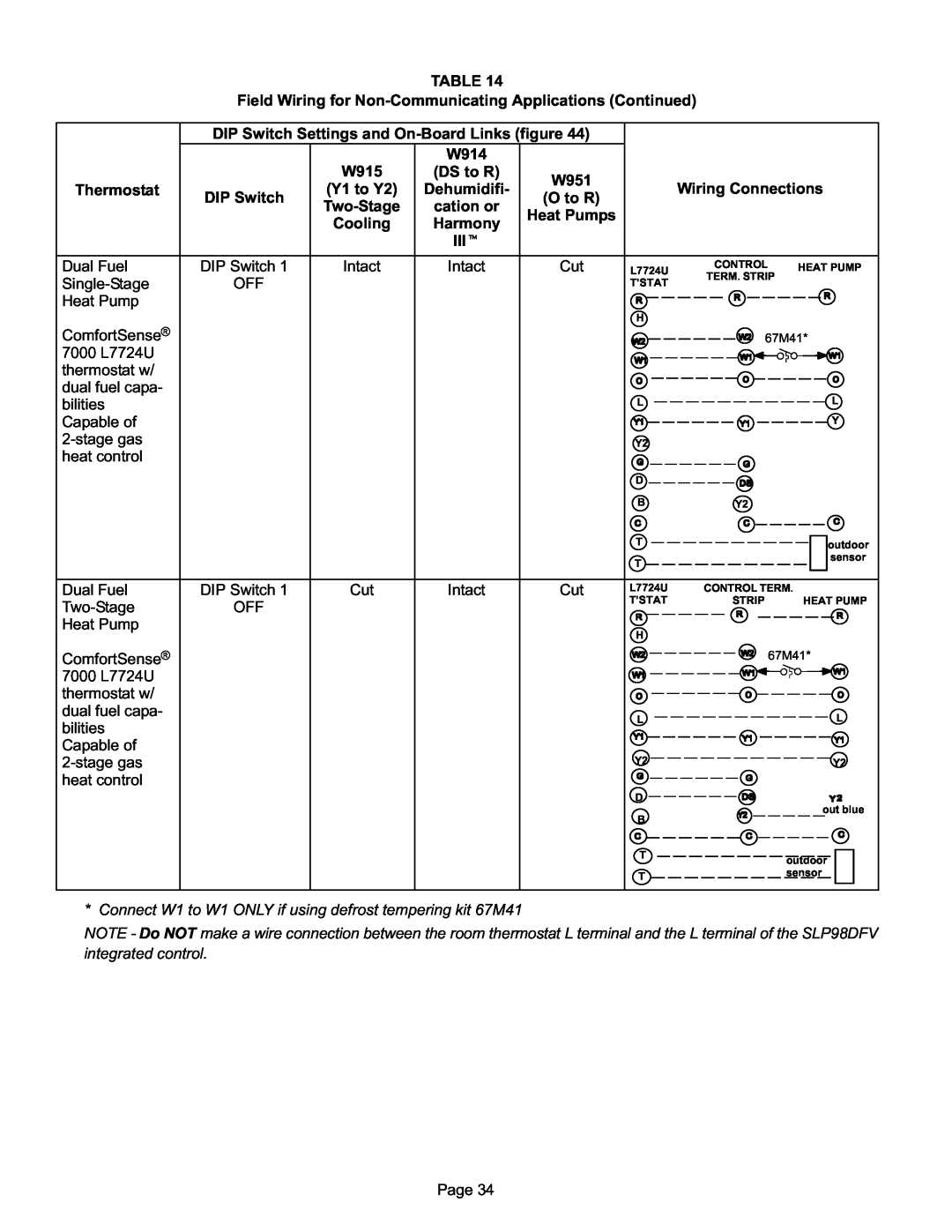
TABLE 14
Field Wiring for Non−Communicating Applications (Continued)
Thermostat
DIP Switch Settings and On−Board Links (figure 44)
|
| W914 |
| |
| W915 | (DS to R) | W951 | |
| (Y1 to Y2) | Dehumidifi- | ||
DIP Switch | (O to R) | |||
Two−Stage | cation or | |||
| Heat Pumps | |||
| Cooling | Harmony | ||
|
| |||
|
| IIIt |
| |
|
|
|
|
Wiring Connections
Dual Fuel | DIP Switch 1 | Intact | Intact | Cut | L7724U | CONTROL | HEAT PUMP | |
|
| |||||||
Single−Stage | OFF |
|
|
| T’STAT | TERM. STRIP | ||
|
|
|
|
|
| |||
Heat Pump |
|
|
|
|
|
|
|
|
|
|
|
|
| H |
|
|
|
ComfortSense® |
|
|
|
|
|
| 67M41* | |
7000 L7724U |
|
|
|
|
|
|
|
|
thermostat w/ |
|
|
|
|
|
|
|
|
dual fuel capa- |
|
|
|
|
|
|
|
|
bilities |
|
|
|
| L |
|
| L |
Capable of |
|
|
|
|
|
|
| Y |
2−stage gas |
|
|
|
| Y2 |
|
|
|
heat control |
|
|
|
|
|
|
|
|
|
|
|
|
| D |
|
|
|
|
|
|
|
| B | Y2 |
|
|
|
|
|
|
| T |
|
| outdoor |
|
|
|
|
|
|
|
| |
|
|
|
|
| T |
|
| sensor |
|
|
|
|
|
|
|
| |
Dual Fuel | DIP Switch 1 | Cut | Intact | Cut | L7724U | CONTROL TERM. | ||
Two−Stage | OFF |
|
|
| T’STAT | STRIP |
| HEAT PUMP |
|
|
|
|
|
|
| ||
Heat Pump |
|
|
|
| H |
|
|
|
|
|
|
|
|
|
|
| |
ComfortSense® |
|
|
|
|
|
|
| 67M41* |
7000 L7724U |
|
|
|
|
|
|
|
|
thermostat w/ |
|
|
|
|
|
|
|
|
dual fuel capa- |
|
|
|
| L |
|
| L |
bilities |
|
|
|
|
|
| ||
|
|
|
|
|
|
|
| |
Capable of |
|
|
|
|
|
|
|
|
2−stage gas |
|
|
|
| Y2 |
|
| Y2 |
heat control |
|
|
|
|
|
|
|
|
|
|
|
|
| D |
|
|
|
|
|
|
|
| B |
|
| out blue |
|
|
|
|
|
|
|
| |
|
|
|
|
| T |
|
| outdoor |
|
|
|
|
|
|
|
| |
|
|
|
|
| T |
|
| sensor |
|
|
|
|
|
|
|
| |
* Connect W1 to W1 ONLY if using defrost tempering kit 67M41
NOTE − Do NOT make a wire connection between the room thermostat L terminal and the L terminal of the SLP98DFV
integrated control.
Page 34