INSTALLATION

INSTALACION

INSTALLATION

WARNING

BUILDUP OF SHIELDING GAS may harm health or kill.

• Shut off shielding gas supply when not in use.

SEE AMERICAN NATIONAL STANDARD Z- 49.1, “SAFETY IN WELDING AND CUT-

TING” PUBLISHED BY THE AMERICAN WELDING SOCIETY.

-------------------------------------------------------------------------------

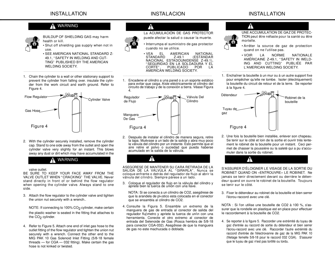
1.Chain the cylinder to a wall or other stationary support to prevent the cylinder from falling over. insulate the cylin- der from the work circuit and earth ground. Refer to Figure 4.

ADVERTENCIA

La ACUMULACIÓN DE GAS PROTECTOR puede afectar la salud o causar la muerte.

• Interrumpa el suministro de gas protector cuando no se utilice.

• VEA EL AMERICAN NATIONAL

STANDARD Z-49.1 (ESTÁNDAR NACIONAL ESTADOUNIDENSE Z-49.1),

“SEGURIDAD EN LA SOLDADURA Y EL CORTE”, PUBLICADO POR LA AMERICAN WELDING SOCIETY.

-------------------------------------------------------------------------------

1.Encadene el cilindro a una pared o a un soporte estático para evitar que caiga. Aísle eléctricamente el cilindro del circuito de trabajo y de la conexión a tierra. Véase Figura 4.

AVERTISSEMENT

UNE ACCUMULATION DE GAZ DE PROTEC- TION peut être néfaste pour la santé ou être mortelle.

Arrêter la source de gaz de protection quand on ne l'utilise pas.

VOIR LA NORME NATIONALE AMÉRICAINE Z-49.1, “SAFETY IN WELD-

ING AND CUTTING” PUBLIÉE PAR L'AMERICAN WELDING SOCIETY.

-------------------------------------------------------------------------------

1.Enchaîner la bouteille à un mur ou à un autre support fixe pour empêcher qu'elle ne tombe. Isoler (électriquement) la bouteille du circuit de retour et de la terre. Se reporter à la figure 4.

Flow Regulator

Cylinder Valve

Gas Hose

Figure 4

Regulador

de Flujo

Manguera

De Gas

Figura 4

Válvula Del Cilindro

Détendeur

Robinet de la bouteille

Tuyau de gaz

Figure 4

2.With the cylinder securely installed, remove the cylinder cap. Stand to one side away from the outlet and open the cylinder valve very slightly for an instant. This blows away any dust or dirt which may have accumulated in the

WARNING

valve outlet.

BE SURE TO KEEP YOUR FACE AWAY FROM THE VALVE OUTLET WHEN “CRACKING” THE VALVE. Never stand directly in front of or behind the flow regulator when opening the cylinder valve. Always stand to one side.

3.Attach the flow regulator to the cylinder valve and tighten the union nut securely with a wrench..

NOTE: If connecting to 100% CO2 cylinder, make certain the plastic washer is seated in the fitting that attaches to the CO2 cylinder.

4.Refer to Figure 5. Attach one end of inlet gas hose to the outlet fitting of the flow regulator and tighten the union nut securely with a wrench. Connect the other end to the MIG PAK 10 Gas Solenoid Inlet Fitting (5/8-18 female threads — for CGA — 032 fitting). Make certain the gas hose is not kinked or twisted.

2.Después de instalar el cilindro de manera segura, retire la tapa. Muévase a un lado de la salida y abra muy poco la válvula del cilindro por un instante. Esto permite que el aire retire el polvo o suciedad que pueda haberse acumulado en la salida de la válvula.

ADVERTENCIA

ASEGÚRESE DE MANTENER SU CARA RETIRADA DE LA SALIDA DE LA VÁLVULA AL “GIRARLA”. Nunca se coloque enfrente o detrás del regulador de flujo al abrir la válvula del cilindro. Siempre párese a un lado.

3.Coloque el regulador de flujo en la válvula del cilindro y apriete bien la tuerca de unión con una llave.

NOTA: Si se conecta a un cilindro de CO2, asegdrese de que la arandela de pl<stico esta colocada en el conector que se ensambla al cilindro de CO2.

4.Consulte la Figura 5. Ensamble un extremo de la manguera de gas de entrada al conector de salida del regulador fluj\metro y apriete la tuerca de uni\n con una herramienta. Conecte el otro extremo al conector de entrada del Selenoide de Gas (Rosca hembra de 5/8-18 para conector CGA-032). Asegdrese de que la manguera de gas no este machucada o doblada.

15

2.Une fois la bouteille bien installée, enlever son chapeau. Se tenir sur le côté et loin de la sortie et ouvrir très lente- ment le robinet de la bouteille pour un instant. Ceci per- met de chasser la poussière ou la saleté qui a pu s'accu- muler dans la sortie du robinet.

AVERTISSEMENT

S'ASSURER D'ÉLOIGNER LE VISAGE DE LA SORTIE DU ROBINET QUAND ON «ENTROUVRE» LE ROBINET. Ne jamais se tenir directement devant ou derrière le déten- deur quand on ouvre le robinet de la bouteille. Toujours se tenir sur le côté.

3.Fixer le détendeur au robinet de la bouteille et bien serrer l'écrou-raccord avec une clé.

NOTA : Si l'on utilise une bouteille de CO2 à 100 %, s'as- surer que la rondelle en plastique est en place pour effectuer le raccordement à la bouteille de CO2.

4.Se reporter à la figure 5. Raccorder une extrémité du tuyau de gaz d'entrée au raccord de sortie du détendeur et bien serrer l'écrou-raccord avec une clé. Raccorder l'autre extrémité du raccord d'entrée de l'électrovanne de gaz de la MIG PAK 10 (filetage femelle 5/8-18 pour le raccord 032 CGA). S'assurer que le tuyau de gaz n'est pas tortillé ou tordu.

Page 15
Image 15
Lincoln Electric MIG-PAK 10 manual Figura, Valve outlet

MIG-PAK 10 specifications

The Lincoln Electric MIG-PAK 10 is a versatile and user-friendly MIG welding machine tailored for light industrial applications and DIY enthusiasts. This compact welder is designed for both professionals and hobbyists, offering a perfect blend of performance and portability. It is particularly suitable for welding light to medium-gauge steel, stainless steel, and aluminum.

One of the standout features of the MIG-PAK 10 is its economy of size without compromising on power. Weighing in at just around 40 pounds, it is easily transportable, making it a practical choice for on-site jobs or small workshops. Its compact dimensions allow it to fit into tight spaces, facilitating accessibility for various welding tasks.

The MIG-PAK 10 employs a built-in gas solenoid that facilitates gas shielding for improved arc stability and weld quality. It is compatible with both shielding gas and flux-cored wire, offering flexibility depending on the application requirements and working environment. This dual capability is particularly beneficial for outdoor welding, where wind can disrupt gas shielding.

Lincoln Electric has integrated an adjustable output that offers a wide range of voltage settings, allowing users to fine-tune their settings for different materials and thicknesses. This feature, accompanied by a smooth and stable arc, contributes to high-quality welds and ease of operation.

Ease of use is further enhanced by the machine’s simple control panel, which features clear indicators and settings. Novice welders will appreciate the intuitive layout, while experienced users will value the precision controls for intricate tasks.

Another key technology utilized in the MIG-PAK 10 is Lincoln Electric’s professional-grade drive system, which ensures reliable wire feed performance. This system minimizes downtime and improves welding efficiency by reducing the chances of wire tangling or feeding issues.

Finally, the MIG-PAK 10 is constructed with durability in mind. Its robust casing is designed to withstand the rigors of welding environments, ensuring longevity and consistent performance.

In summary, the Lincoln Electric MIG-PAK 10 is a well-rounded MIG welder suitable for various welding needs. Its exceptional portability, dual wire feeding options, adjustable output, user-friendly controls, and sturdy construction make it a compelling choice for both beginners and professionals in the welding industry.