INSTALLATION

INSTALACIÓN

INSTALLATION

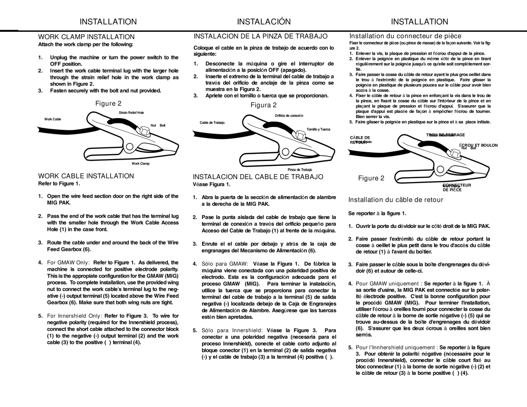
WORK CLAMP INSTALLATION

Attach the work clamp per the following:

1.Unplug the machine or turn the power switch to the OFF position.

2.Insert the work cable terminal lug with the larger hole through the strain relief hole in the work clamp as shown in Figure 2.

3.Fasten securely with the bolt and nut provided.

Figure 2

Strain Relief Hole

Work Cable

Nut & Bolt

INSTALACION DE LA PINZA DE TRABAJO

Coloque el cable en la pinza de trabajo de acuerdo con lo siguiente:

1.Desconecte la máquina o gire el interruptor de alimentación a la posición OFF (apagado).

2.Inserte el extremo de la terminal del cable de trabajo a través del orificio de anclaje de la pinza como se muestra en la Figura 2.

3.Apriete con el tornillo o tuerca que se proporcionan.

Figura 2

Orificio de conexión

Cable de Trabajo

Tornillo y Tuerca

Installation du connecteur de pièce

Fixer le connecteur de pièce (ou pince de masse) de la façon suivante. Voir la fig- ure 2.

1.Enlever la vis, la plaque de pression et l'écrou d'appui de la pince.

2.Enlever la poignée en plastique du même côté de la pince en tirant régulièrement sur la poignée jusqu'à ce qu'elle soit complètement sor- tie.

3.Faire passer la cosse du câble de retour ayant le plus gros oeillet dans le trou à l'extrémité de la poignée en plastique. Faire glisser la poignée en plastique de plusieurs pouces sur le câble pour avoir bien accès à la cosse.

4.Fixer le câble de retour à la pince en enfonçant la vis dans le trou de la pince, en fixant la cosse du câble sur l'intérieur de la pince et en plaçant la plaque de pression et l'écrou d'appui. S'assurer que la plaque d'appui est placée de façon à empêcher l'écrou de tourner. Bien serrer la vis.

5.Faire glisser la poignée en plastique sur la pince et à sa place initiale.

Work Clamp

Pinza de Trabajo

CÂBLE DE RETOUR

TROU DE SERRAGE

ÉCROU ET BOULON

WORK CABLE INSTALLATION

Refer to Figure 1.

1.Open the wire feed section door on the right side of the

MIG PAK.

2.Pass the end of the work cable that has the terminal lug with the smaller hole through the Work Cable Access Hole (1) in the case front.

3.Route the cable under and around the back of the Wire Feed Gearbox (6).

4.For GMAW Only: Refer to Figure 1. As delivered, the machine is connected for positive electrode polarity. This is the appropiate configuration for the GMAW (MIG) process. To complete installation, use the provided wing nut to connect the work cable’s terminal lug to the neg- ative (-) output terminal (5) located above the Wire Feed Gearbox (6). Make sure that both wing nuts are tight.

5.For Innershield Only: Refer to Figure 3. To wire for negative polarity (required for the Innershield process), connect the short cable attached to the connector block

(1)to the negative (-) output terminal (2) and the work cable (3) to the positive (+) terminal (4).

INSTALACION DEL CABLE DE TRABAJO

Véase Figura 1.

1.Abra la puerta de la sección de alimentación de alambre a la derecha de la MIG PAK.

2.Pase la punta aislada del cable de trabajo que tiene la terminal de conexión a través del orificio pequeño para Acceso del Cable de Trabajo (1) al frente de la máquina.

3.Enrute el el cable por debajo y atrás de la caja de engranages del Mecanismo de Alimentación (6).

4.Sólo para GMAW: Véase la Figura 1. De fábrica la máquina viene conectada con una polaridad positiva de electrodo. Esta es la configuración adecuada para el proceso GMAW (MIG). Para terminar la instalación, utilice la tuerca que se proporciona para conectar la terminal del cable de trabajo a la terminal (5) de salida negativa (-) localizada debajo de la Caja de Engranajes de Alimentación de Alambre. Asegúrese que las tuercas estén bien apretadas.

5.Sólo para Innershield: Véase la Figure 3. Para conectar a una polaridad negativa (necesaria para el proceso Innershield), conecte el cable corto adjunto al bloque conector (1) en la terminal (2) de salida negativa (-) y el cable de trabajo (3) a la terminal (4) positiva (+).

Figure 2

CONNECTEUR

DE PIÈCE

Installation du câble de retour

Se reporter à la figure 1.

1.Ouvrir la porte du dévidoir sur le côté droit de la MIG PAK.

2.Faire passer l'extrémité du câble de retour portant la cosse à oeillet le plus petit dans le trou d'accès du câble de retour (1) à l'avant du boîtier.

3.Faire passer le câble sous la boîte d'engrenages du dévi- doir (6) et autour de celle-ci.

4.Pour GMAW uniquement : Se reporter à la figure 1. À sa sortie d'usine, la MIG PAK est connectée sur la polar- ité électrode positive. C'est la bonne configuration pour le procédé GMAW (MIG). Pour terminer l'installation, utiliser l'écrou à oreilles fourni pour connecter la cosse du câble de retour à la borne de sortie négative (-) (5) qui se trouve au-dessus de la boîte d'engrenages du dévidoir

(6). S'assurer que les deux écrous à oreilles sont bien serrés.

5.Pour l'Innhershield uniquement : Se reporter à la figure 3. Pour obtenir la polarité négative (nécessaire pour le procédé Innershield), connecter le câble court fixé au bloc connecteur (1) à la borne de sortie négative (-) (2) et le câble de retour (3) à la borne positive (+) (4).

12

Page 12
Image 12
Lincoln Electric MIG-PAK 10 manual Work Clamp Installation, Instalacion DE LA Pinza DE Trabajo, Work Cable Installation

MIG-PAK 10 specifications

The Lincoln Electric MIG-PAK 10 is a versatile and user-friendly MIG welding machine tailored for light industrial applications and DIY enthusiasts. This compact welder is designed for both professionals and hobbyists, offering a perfect blend of performance and portability. It is particularly suitable for welding light to medium-gauge steel, stainless steel, and aluminum.

One of the standout features of the MIG-PAK 10 is its economy of size without compromising on power. Weighing in at just around 40 pounds, it is easily transportable, making it a practical choice for on-site jobs or small workshops. Its compact dimensions allow it to fit into tight spaces, facilitating accessibility for various welding tasks.

The MIG-PAK 10 employs a built-in gas solenoid that facilitates gas shielding for improved arc stability and weld quality. It is compatible with both shielding gas and flux-cored wire, offering flexibility depending on the application requirements and working environment. This dual capability is particularly beneficial for outdoor welding, where wind can disrupt gas shielding.

Lincoln Electric has integrated an adjustable output that offers a wide range of voltage settings, allowing users to fine-tune their settings for different materials and thicknesses. This feature, accompanied by a smooth and stable arc, contributes to high-quality welds and ease of operation.

Ease of use is further enhanced by the machine’s simple control panel, which features clear indicators and settings. Novice welders will appreciate the intuitive layout, while experienced users will value the precision controls for intricate tasks.

Another key technology utilized in the MIG-PAK 10 is Lincoln Electric’s professional-grade drive system, which ensures reliable wire feed performance. This system minimizes downtime and improves welding efficiency by reducing the chances of wire tangling or feeding issues.

Finally, the MIG-PAK 10 is constructed with durability in mind. Its robust casing is designed to withstand the rigors of welding environments, ensuring longevity and consistent performance.

In summary, the Lincoln Electric MIG-PAK 10 is a well-rounded MIG welder suitable for various welding needs. Its exceptional portability, dual wire feeding options, adjustable output, user-friendly controls, and sturdy construction make it a compelling choice for both beginners and professionals in the welding industry.