OPERATION

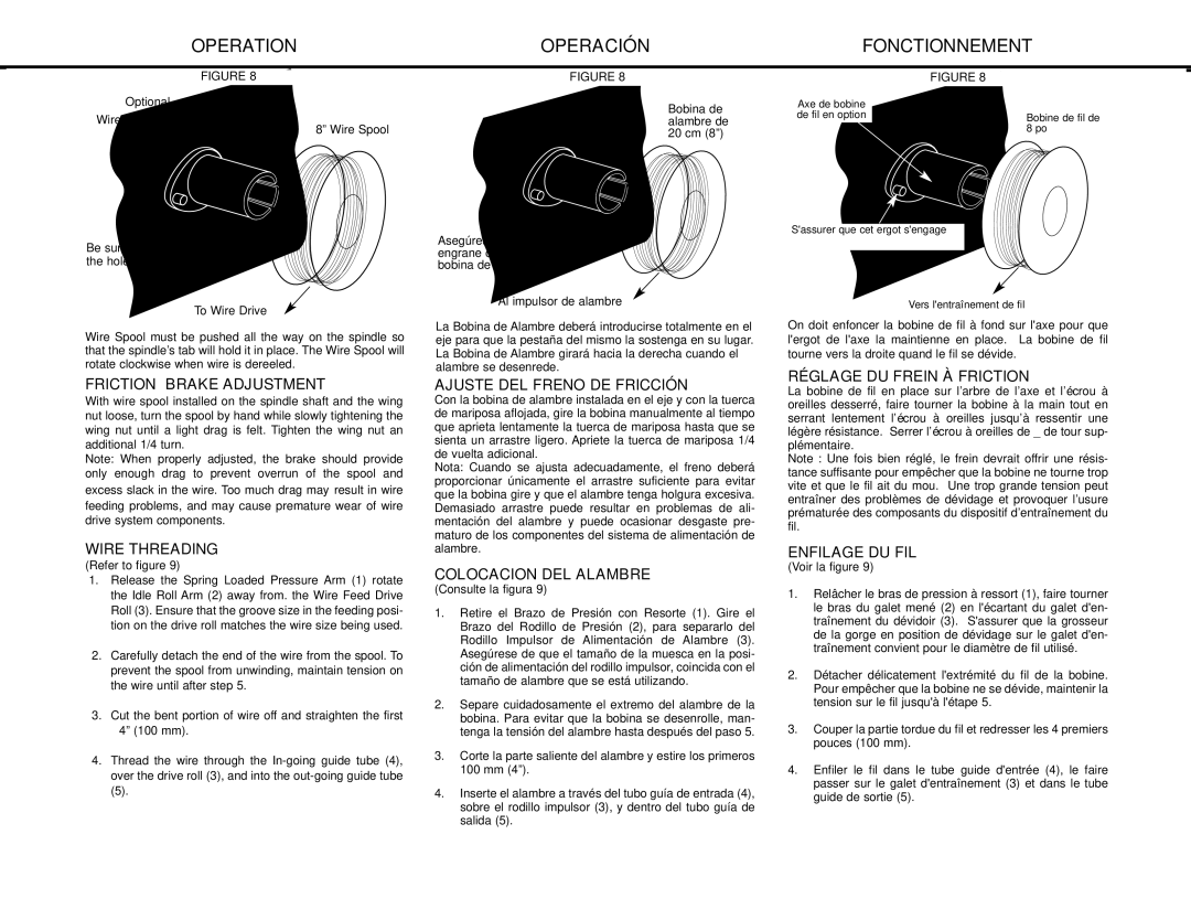
FIGURE 8

Optional

Wire Spool Spindle

8” Wire Spool

Be sure that this stud engages the hole in the wire spool.

To Wire Drive

Wire Spool must be pushed all the way on the spindle so that the spindle’s tab will hold it in place. The Wire Spool will rotate clockwise when wire is dereeled.

FRICTION BRAKE ADJUSTMENT

With wire spool installed on the spindle shaft and the wing nut loose, turn the spool by hand while slowly tightening the wing nut until a light drag is felt. Tighten the wing nut an additional 1/4 turn.

Note: When properly adjusted, the brake should provide only enough drag to prevent overrun of the spool and excess slack in the wire. Too much drag may result in wire feeding problems, and may cause premature wear of wire drive system components.

WIRE THREADING

(Refer to figure 9)

1.Release the Spring Loaded Pressure Arm (1) rotate the Idle Roll Arm (2) away from. the Wire Feed Drive Roll (3). Ensure that the groove size in the feeding posi- tion on the drive roll matches the wire size being used.

2.Carefully detach the end of the wire from the spool. To prevent the spool from unwinding, maintain tension on the wire until after step 5.

3.Cut the bent portion of wire off and straighten the first 4” (100 mm).

4.Thread the wire through the In-going guide tube (4), over the drive roll (3), and into the out-going guide tube

(5).

OPERACIÓN

FIGURE 8

Bobina de alambre de 20 cm (8”)

Asegúrese de que el borne engrane con el orificio de la bobina de alambre.

Al impulsor de alambre

La Bobina de Alambre deberá introducirse totalmente en el eje para que la pestaña del mismo la sostenga en su lugar. La Bobina de Alambre girará hacia la derecha cuando el alambre se desenrede.

AJUSTE DEL FRENO DE FRICCIÓN

Con la bobina de alambre instalada en el eje y con la tuerca de mariposa aflojada, gire la bobina manualmente al tiempo que aprieta lentamente la tuerca de mariposa hasta que se sienta un arrastre ligero. Apriete la tuerca de mariposa 1/4 de vuelta adicional.

Nota: Cuando se ajusta adecuadamente, el freno deberá proporcionar únicamente el arrastre suficiente para evitar que la bobina gire y que el alambre tenga holgura excesiva. Demasiado arrastre puede resultar en problemas de ali- mentación del alambre y puede ocasionar desgaste pre- maturo de los componentes del sistema de alimentación de alambre.

COLOCACION DEL ALAMBRE

(Consulte la figura 9)

1.Retire el Brazo de Presión con Resorte (1). Gire el Brazo del Rodillo de Presión (2), para separarlo del Rodillo Impulsor de Alimentación de Alambre (3). Asegúrese de que el tamaño de la muesca en la posi- ción de alimentación del rodillo impulsor, coincida con el tamaño de alambre que se está utilizando.

2.Separe cuidadosamente el extremo del alambre de la bobina. Para evitar que la bobina se desenrolle, man- tenga la tensión del alambre hasta después del paso 5.

3.Corte la parte saliente del alambre y estire los primeros 100 mm (4”).

4.Inserte el alambre a través del tubo guía de entrada (4), sobre el rodillo impulsor (3), y dentro del tubo guía de salida (5).

FONCTIONNEMENT

FIGURE 8

Axe de bobine

de fil en optionBobine de fil de 8 po

S'assurer que cet ergot s'engage

Vers l'entraînement de fil

On doit enfoncer la bobine de fil à fond sur l'axe pour que l'ergot de l'axe la maintienne en place. La bobine de fil tourne vers la droite quand le fil se dévide.

RÉGLAGE DU FREIN À FRICTION

La bobine de fil en place sur l’arbre de l’axe et l’écrou à oreilles desserré, faire tourner la bobine à la main tout en serrant lentement l’écrou à oreilles jusqu’à ressentir une légère résistance. Serrer l’écrou à oreilles de _ de tour sup- plémentaire.

Note : Une fois bien réglé, le frein devrait offrir une résis- tance suffisante pour empêcher que la bobine ne tourne trop vite et que le fil ait du mou. Une trop grande tension peut entraîner des problèmes de dévidage et provoquer l’usure prématurée des composants du dispositif d’entraînement du fil.

ENFILAGE DU FIL

(Voir la figure 9)

1.Relâcher le bras de pression à ressort (1), faire tourner le bras du galet mené (2) en l'écartant du galet d'en- traînement du dévidoir (3). S'assurer que la grosseur de la gorge en position de dévidage sur le galet d'en- traînement convient pour le diamètre de fil utilisé.

2.Détacher délicatement l'extrémité du fil de la bobine. Pour empêcher que la bobine ne se dévide, maintenir la tension sur le fil jusqu'à l'étape 5.

3.Couper la partie tordue du fil et redresser les 4 premiers pouces (100 mm).

4.Enfiler le fil dans le tube guide d'entrée (4), le faire passer sur le galet d'entraînement (3) et dans le tube guide de sortie (5).

22

Page 22
Image 22
Lincoln Electric MIG-PAK 10 manual Friction Brake Adjustment, Wire Threading, Ajuste DEL Freno DE Fricción, Enfilage DU FIL

MIG-PAK 10 specifications

The Lincoln Electric MIG-PAK 10 is a versatile and user-friendly MIG welding machine tailored for light industrial applications and DIY enthusiasts. This compact welder is designed for both professionals and hobbyists, offering a perfect blend of performance and portability. It is particularly suitable for welding light to medium-gauge steel, stainless steel, and aluminum.

One of the standout features of the MIG-PAK 10 is its economy of size without compromising on power. Weighing in at just around 40 pounds, it is easily transportable, making it a practical choice for on-site jobs or small workshops. Its compact dimensions allow it to fit into tight spaces, facilitating accessibility for various welding tasks.

The MIG-PAK 10 employs a built-in gas solenoid that facilitates gas shielding for improved arc stability and weld quality. It is compatible with both shielding gas and flux-cored wire, offering flexibility depending on the application requirements and working environment. This dual capability is particularly beneficial for outdoor welding, where wind can disrupt gas shielding.

Lincoln Electric has integrated an adjustable output that offers a wide range of voltage settings, allowing users to fine-tune their settings for different materials and thicknesses. This feature, accompanied by a smooth and stable arc, contributes to high-quality welds and ease of operation.

Ease of use is further enhanced by the machine’s simple control panel, which features clear indicators and settings. Novice welders will appreciate the intuitive layout, while experienced users will value the precision controls for intricate tasks.

Another key technology utilized in the MIG-PAK 10 is Lincoln Electric’s professional-grade drive system, which ensures reliable wire feed performance. This system minimizes downtime and improves welding efficiency by reducing the chances of wire tangling or feeding issues.

Finally, the MIG-PAK 10 is constructed with durability in mind. Its robust casing is designed to withstand the rigors of welding environments, ensuring longevity and consistent performance.

In summary, the Lincoln Electric MIG-PAK 10 is a well-rounded MIG welder suitable for various welding needs. Its exceptional portability, dual wire feeding options, adjustable output, user-friendly controls, and sturdy construction make it a compelling choice for both beginners and professionals in the welding industry.