CHANGING LINER
NOTICE: The variation in cable lengths prevents the inter- changeability of liners. Once a liner has been cut for a par- ticular gun, it should not be installed in another gun unless it can meet the liner cutoff length requirement. Refer to Figure below.
1.Remove the gas nozzle from the gun by unscrewing counter-clockwise.
2.Remove the existing contact tip from the gun by unscrew- ing counter-clockwise.
3.Remove the gas diffuser from the gun tube by unscrew- ing counter-clockwise.
4.Lay the gun and cable out straight on a flat surface. Loosen the set screw located in the brass connector at the wire feeder end of the cable. Pull the liner out of the cable.
5.Insert a new untrimmed liner into the connector end of the cable. Be sure the liner bushing is stenciled appropriate- ly for the wire size being used.
6.Fully seat the liner bushing into the connector. Tighten the set screw on the brass cable connector. At this time, the gas diffuser should not be installed onto the end of the gun tube.
7.With the gas nozzle and diffuser removed from the gun tube, be sure the cable is straight, and then trim the liner to the length shown in the Figure below. Remove any burrs from the end of the liner.
8.Screw the gas diffuser onto the end of the gun tube and securely tighten.
9.Replace the contact tip and nozzle.
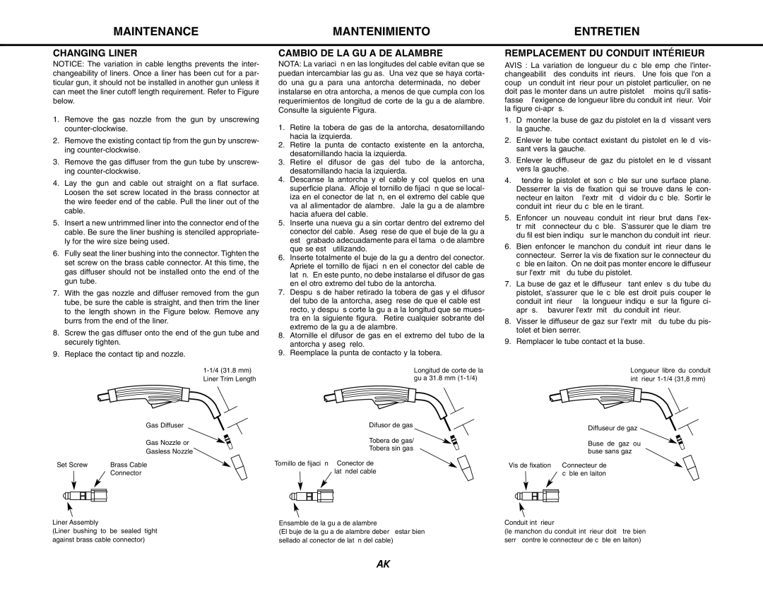
1-1/4 (31.8 mm) Liner Trim Length
| Gas Diffuser |
| Gas Nozzle or |
| Gasless Nozzle |
Set Screw | Brass Cable |
| Connector |
Liner Assembly
(Liner bushing to be sealed tight against brass cable connector)
CAMBIO DE LA GUÍA DE ALAMBRE
NOTA: La variación en las longitudes del cable evitan que se puedan intercambiar las guías. Una vez que se haya corta- do una guía para una antorcha determinada, no deberá instalarse en otra antorcha, a menos de que cumpla con los requerimientos de longitud de corte de la guía de alambre. Consulte la siguiente Figura.
1.Retire la tobera de gas de la antorcha, desatornillando hacia la izquierda.
2.Retire la punta de contacto existente en la antorcha, desatornillando hacia la izquierda.
3.Retire el difusor de gas del tubo de la antorcha, desatornillando hacia la izquierda.
4.Descanse la antorcha y el cable y colóquelos en una superficie plana. Afloje el tornillo de fijación que se local- iza en el conector de latón, en el extremo del cable que va al alimentador de alambre. Jale la guía de alambre hacia afuera del cable.
5.Inserte una nueva guía sin cortar dentro del extremo del conector del cable. Asegúrese de que el buje de la guía esté grabado adecuadamente para el tamaño de alambre que se está utilizando.
6.Inserte totalmente el buje de la guía dentro del conector. Apriete el tornillo de fijación en el conector del cable de latón. En este punto, no debe instalarse el difusor de gas en el otro extremo del tubo de la antorcha.
7.Después de haber retirado la tobera de gas y el difusor del tubo de la antorcha, asegúrese de que el cable esté recto, y después corte la guía a la longitud que se mues- tra en la siguiente figura. Retire cualquier sobrante del extremo de la guía de alambre.
8.Atornille el difusor de gas en el extremo del tubo de la antorcha y asegúrelo.
9.Reemplace la punta de contacto y la tobera.
Longitud de corte de la guía 31.8 mm (1-1/4)
Difusor de gas
Tobera de gas/
Tobera sin gas
Tornillo de fijación Conector de latóndel cable
Ensamble de la guía de alambre
(El buje de la guía de alambre deberá estar bien sellado al conector de latón del cable)
REMPLACEMENT DU CONDUIT INTÉRIEUR
AVIS : La variation de longueur du câble empêche l'inter- changeabilité des conduits intérieurs. Une fois que l'on a coupé un conduit intérieur pour un pistolet particulier, on ne doit pas le monter dans un autre pistolet à moins qu'il satis- fasse à l'exigence de longueur libre du conduit intérieur. Voir la figure ci-après.
1.Démonter la buse de gaz du pistolet en la dévissant vers la gauche.
2.Enlever le tube contact existant du pistolet en le dévis- sant vers la gauche.
3.Enlever le diffuseur de gaz du pistolet en le dévissant vers la gauche.
4.Étendre le pistolet et son câble sur une surface plane. Desserrer la vis de fixation qui se trouve dans le con- necteur en laiton à l'extrémité dévidoir du câble. Sortir le conduit intérieur du câble en le tirant.
5.Enfoncer un nouveau conduit intérieur brut dans l'ex- trémité connecteur du câble. S'assurer que le diamètre du fil est bien indiqué sur le manchon du conduit intérieur.
6.Bien enfoncer le manchon du conduit intérieur dans le connecteur. Serrer la vis de fixation sur le connecteur du câble en laiton. On ne doit pas monter encore le diffuseur sur l'extrémité du tube du pistolet.
7.La buse de gaz et le diffuseur étant enlevés du tube du pistolet, s'assurer que le câble est droit puis couper le conduit intérieur à la longueur indiquée sur la figure ci- après. Ébavurer l'extrémité du conduit intérieur.
8.Visser le diffuseur de gaz sur l'extrémité du tube du pis- tolet et bien serrer.
9.Remplacer le tube contact et la buse.
Longueur libre du conduit intérieur 1-1/4 (31,8 mm)
Diffuseur de gaz
Buse de gaz ou buse sans gaz
Vis de fixation Connecteur de câble en laiton
Conduit intérieur
(le manchon du conduit intérieur doit être bien serré contre le connecteur de câble en laiton)