INSTALLATION |
Return to Section TOC
Section TOC
DIGITAL CONTROL CABLE, K1543-XX
(See Figure A.3)
ArcLink/LincNet control cables are special high quality cables for digital communication. The cables are cop- per 5 conductor cable in a
Use of
The control cables connect the power source to the wire feeder, and the wire feeder to other wire feeders.
Control cables may be connected end to end to extend their length. Use a maximum of 200 ft. (61.0m) of con- trol cable between components.
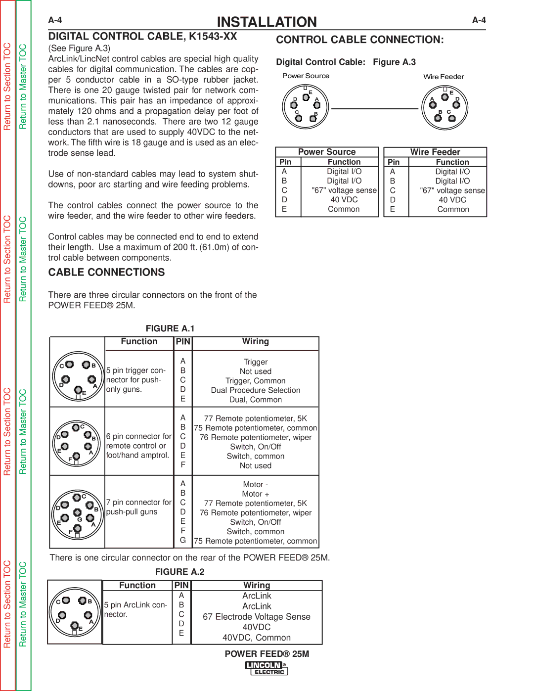
CONTROL CABLE CONNECTION:
Digital Control Cable: Figure A.3
Power Source | Wire Feeder |
D | E A | A | E D |
C | B | B | C |
| Power Source |
| Wire Feeder |
Pin | Function | Pin | Function |
A | Digital I/O | A | Digital I/O |
B | Digital I/O | B | Digital I/O |
C | "67" voltage sense | C | "67" voltage sense |
D | 40 VDC | D | 40 VDC |
E | Common | E | Common |
Return to
Return to Section TOC
Return to Master TOC
Return to Master TOC
Return to Master TOC
CABLE CONNECTIONS
There are three circular connectors on the front of the
POWER FEED® 25M.
|
|
| FIGURE A.1 | ||
|
|
| Function | PIN | Wiring |
C |
| B | 5 pin trigger con- | A | Trigger |
|
|
| |||
|
|
| B | Not used | |
D | E | A | nector for push- | C | Trigger, Common |
only guns. | D | Dual Procedure Selection | |||
|
|
| E | ||
|
|
|
| Dual, Common | |
| C |
|
| A | 77 Remote potentiometer, 5K |
D | B | 6 pin connector for | B | 75 Remote potentiometer, common | |
| C | 76 Remote potentiometer, wiper | |||
E |
| A | remote control or | D | Switch, On/Off |
F | foot/hand amptrol. | E | Switch, common | ||
|
|
| F | ||
|
|
|
| Not used | |
| C |
|
| A | Motor - |
|
|
| B | Motor + | |
|
| 7 pin connector for | C | ||
D |
| B | 77 Remote potentiometer, 5K | ||
G |
| D | 76 Remote potentiometer, wiper | ||
E | A |
| E | Switch, On/Off | |
| F |
|
| F | Switch, common |
|
|
|
| G | 75 Remote potentiometer, common |
There is one circular connector on the rear of the POWER FEED® 25M.
Return to Section TOC
Return to Master TOC
C |
| B |
D | E | A |
|
|
FIGURE A.2
Function | PIN | Wiring |
| A | ArcLink |
5 pin ArcLink con- | B | ArcLink |
nector. | C | 67 Electrode Voltage Sense |
| D | 40VDC |
| E | |
| 40VDC, Common | |
|
| |
|
|
|