Return to Section TOC
Return to Master TOC
| OPERATION | |||
| Aluminum Pulse and |
| ||
|
|
|
|
|
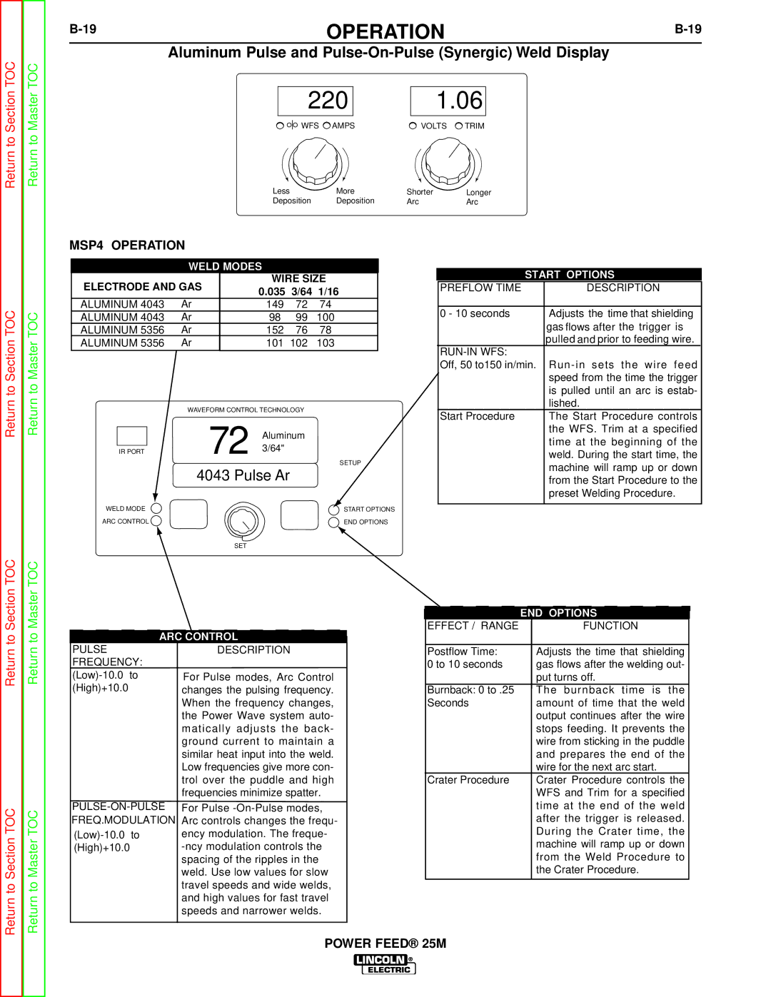
220 1.06
WFS AMPS | VOLTS TRIM |
Less | More | Shorter | Longer |
Deposition | Deposition | Arc | Arc |
Return to Section TOC
Return to Master TOC
MSP4 OPERATION
WELD MODES
ELECTRODE AND GAS | WIRE SIZE | ||||
0.035 | 3/64 | 1/16 | |||
|
| ||||
ALUMINUM 4043 | Ar | 149 | 72 | 74 | |
ALUMINUM 4043 | Ar | 98 | 99 | 100 | |
ALUMINUM 5356 | Ar | 152 | 76 | 78 | |
ALUMINUM 5356 | Ar | 101 | 102 | 103 | |
|
|
|
|
| |
| WAVEFORM CONTROL TECHNOLOGY | ||
| 72 | Aluminum | |
IR PORT | 3/64" | ||
SETUP | |||
|
| ||
| 4043 Pulse Ar | ||
WELD MODE |
| START OPTIONS | |
ARC CONTROL |
| END OPTIONS | |
SET
START OPTIONS | |
|
|
PREFLOW TIME | DESCRIPTION |
|
|
0 - 10 seconds | Adjusts the time that shielding |
| gas flows after the trigger is |
| pulled and prior to feeding wire. |
|
|
Off, 50 to150 in/min. | |
| speed from the time the trigger |
| is pulled until an arc is estab- |
| lished. |
Start Procedure | The Start Procedure controls |
| the WFS. Trim at a specified |
| time at the beginning of the |
| weld. During the start time, the |
| machine will ramp up or down |
| from the Start Procedure to the |
| preset Welding Procedure. |
|
|
to Section TOC
to Master TOC
ARC CONTROL
| END OPTIONS |
EFFECT / RANGE | FUNCTION |
Return
Return to Section TOC
Return
Return to Master TOC
PULSE FREQUENCY:
DESCRIPTION
For Pulse modes, Arc Control changes the pulsing frequency. When the frequency changes, the Power Wave system auto- matically adjusts the back- ground current to maintain a similar heat input into the weld. Low frequencies give more con- trol over the puddle and high frequencies minimize spatter.
For Pulse
Postflow Time: | Adjusts the time that shielding |
0 to 10 seconds | gas flows after the welding out- |
| put turns off. |
Burnback: 0 to .25 | The burnback time is the |
Seconds | amount of time that the weld |
| output continues after the wire |
| stops feeding. It prevents the |
| wire from sticking in the puddle |
| and prepares the end of the |
| wire for the next arc start. |
Crater Procedure | Crater Procedure controls the |
| WFS and Trim for a specified |
| time at the end of the weld |
| after the trigger is released. |
| During the Crater time, the |
| machine will ramp up or down |
| from the Weld Procedure to |
| the Crater Procedure. |