THEORY OF OPERATION | ||
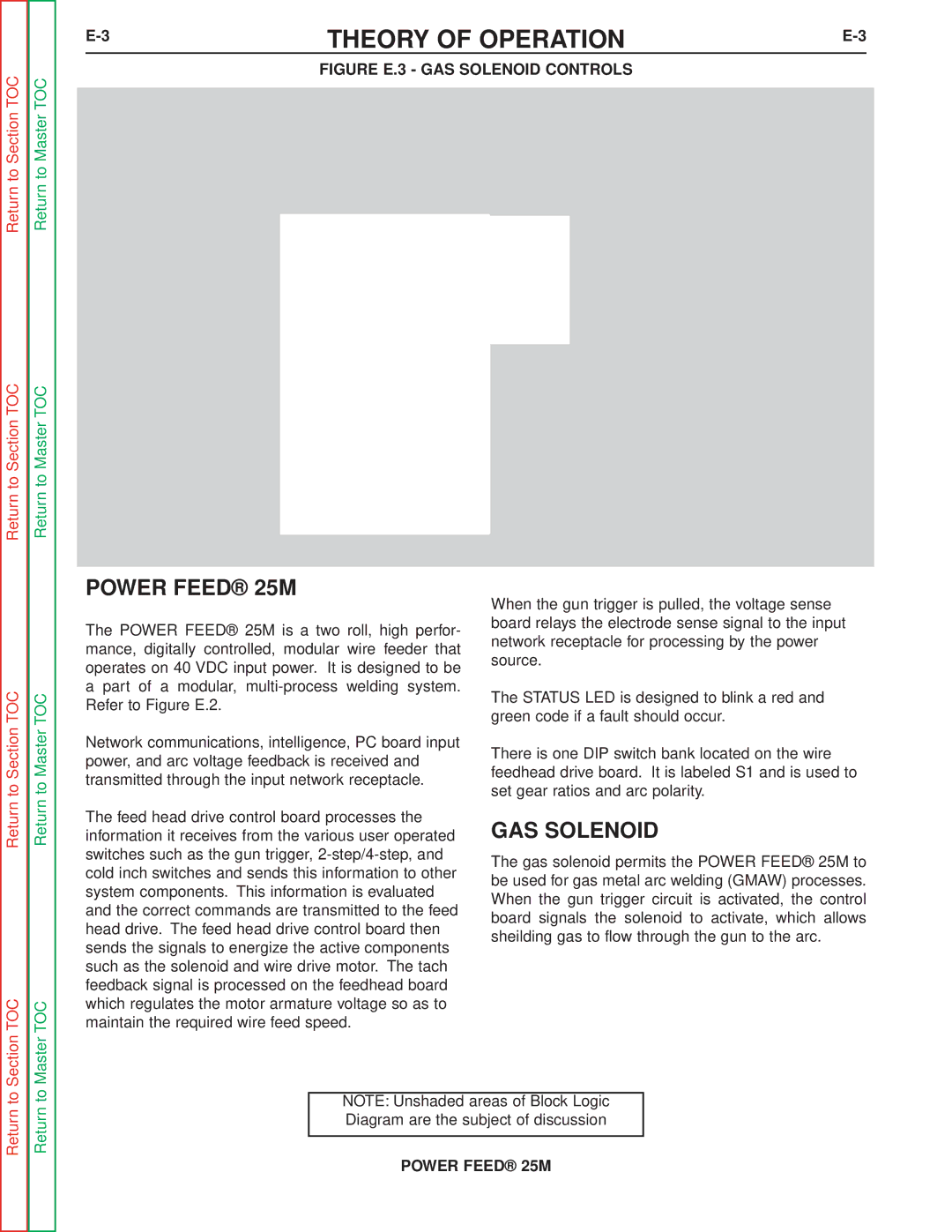
| FIGURE E.3 - GAS SOLENOID CONTROLS |
|
Return to Section TOC
Return to Section TOC
|
| VOLTAGE |
|
|
| SENSE |
|
| LEAD #67A | LEAD #67 | |
| PUSH PULL |
|
|
| DAUGHTER |
| DRIVE |
|
|
| MOTOR |
| CONTROL BOARD |
|
|
TO POWER | FEEDHEAD | FEEDBACK | TACH |
SOURCE |
| ||
|
| ||
|
|
| |
|
| STATUS LED | |
| DIP SWITCHES |
| GUN TIGGER AND |
INPUT |
|
| DUAL PROCEDURE |
NETWORK |
|
| RECEPTACLE |
RECEPTACLE |
|
|
|
|
| HEATER LIGHT | |||||||
|
| ||||||||
|
|
|
|
|
|
|
|
| |
|
|
|
|
|
|
|
|
|
|
CONNECTOR |
|
|
|
|
|
|
|
|
|
FOOT AMPTROL |
| COLD GAS |
| ||||||
|
|
| INCH/ SOLENOID |
| |||||
|
|
|
| GAS |
| ||||
|
|
| PURGE |
| |||||
GEAR BOX
AND
CONDUCTOR
BLOCK
Return to Section TOC
Section TOC
Return to Master TOC
Return to Master TOC
Return to Master TOC
Master TOC
POWER FEED® 25M
The POWER FEED® 25M is a two roll, high perfor- mance, digitally controlled, modular wire feeder that operates on 40 VDC input power. It is designed to be a part of a modular,
Network communications, intelligence, PC board input power, and arc voltage feedback is received and transmitted through the input network receptacle.
The feed head drive control board processes the information it receives from the various user operated switches such as the gun trigger,
When the gun trigger is pulled, the voltage sense board relays the electrode sense signal to the input network receptacle for processing by the power source.
The STATUS LED is designed to blink a red and green code if a fault should occur.
There is one DIP switch bank located on the wire feedhead drive board. It is labeled S1 and is used to set gear ratios and arc polarity.
GAS SOLENOID
The gas solenoid permits the POWER FEED® 25M to be used for gas metal arc welding (GMAW) processes. When the gun trigger circuit is activated, the control board signals the solenoid to activate, which allows sheilding gas to flow through the gun to the arc.
Return to
Return to
NOTE: Unshaded areas of Block Logic Diagram are the subject of discussion