OPERATION |
Return to Section TOC
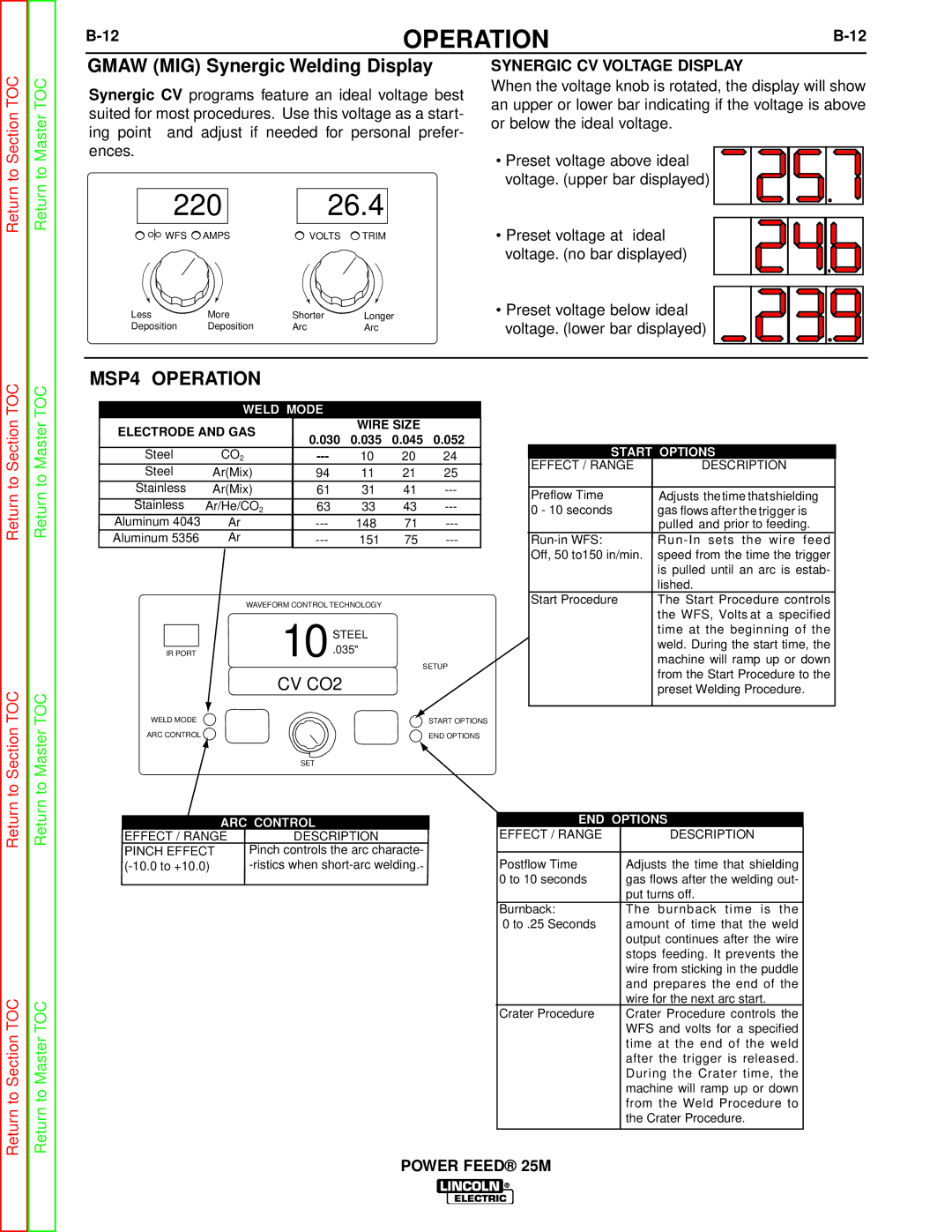
GMAW (MIG) Synergic Welding Display
Synergic CV programs feature an ideal voltage best suited for most procedures. Use this voltage as a start- ing point and adjust if needed for personal prefer- ences.
220 | 26.4 |
WFS AMPS | VOLTS TRIM |
Less | More | Shorter | Longer |
Deposition | Deposition | Arc | Arc |
SYNERGIC CV VOLTAGE DISPLAY
When the voltage knob is rotated, the display will show an upper or lower bar indicating if the voltage is above or below the ideal voltage.
• Preset voltage above ideal voltage. (upper bar displayed)
• Preset voltage at ideal voltage. (no bar displayed)
• Preset voltage below ideal voltage. (lower bar displayed)
Return to Section TOC
to Section TOC
Return to Master TOC
Return to Master TOC
to Master TOC
MSP4 OPERATION
WELD MODE
ELECTRODE AND GAS |
|
| WIRE SIZE |
| |||
0.030 | 0.035 | 0.045 | 0.052 | ||||
|
| ||||||
Steel | CO2 |
| 10 | 20 | 24 | ||
Steel | Ar(Mix) | 94 |
| 11 | 21 | 25 | |
Stainless | Ar(Mix) | 61 |
| 31 | 41 | ||
Stainless | Ar/He/CO2 | 63 |
| 33 | 43 | ||
Aluminum 4043 | Ar |
| 148 | 71 | |||
Aluminum 5356 | Ar |
| 151 | 75 | |||
| WAVEFORM CONTROL TECHNOLOGY |
|
| ||||
|
| 10 | STEEL |
|
| ||
|
|
|
|
| |||
IR PORT |
|
| .035" |
|
| ||
|
|
|
|
| SETUP | ||
|
| CV CO2 |
|
|
| ||
WELD MODE |
|
|
|
|
| START OPTIONS | |
ARC CONTROL |
|
|
|
|
| END OPTIONS | |
|
| SET |
|
|
|
| |
START OPTIONS |
| ||
EFFECT / RANGE |
| DESCRIPTION | |
Preflow Time | Adjusts thetime thatshielding | ||
0 - 10 seconds | gas flows after the trigger is | ||
| pulled | and prior to feeding. | |
sets the wire f eed | |||
Off, 50 to150 in/min. | speed from the time the trigger | ||
| is pulled until an arc is estab- | ||
| lished. |
|
|
Start Procedure | The Start Procedure | control s | |
| the WFS, Volts at a | specified | |
| time at t he beginning of t he | ||
| weld. During the start time, the | ||
machine will ramp up or down from the Start Procedure to the preset Welding Procedure.
ARC CONTROL
EFFECT / RANGE | DESCRIPTION |
PINCH EFFECT | Pinch controls the arc characte- |
END OPTIONS
EFFECT / RANGE |
| DESCRIPTION |
|
| ||
Postflow Time | Adjusts the time that shielding | |||||
0 to 10 seconds | gas flows after the welding out- | |||||
| put turns off. |
|
|
|
| |
Burnback: | The | burnback | time | is t he | ||
0 to .25 Seconds | amount of time that the weld | |||||
| output continues after the wire | |||||
| stops feeding. It prevents the | |||||
| wire from sticking in the puddle | |||||
| and | prepares the | end | of the | ||
| wire for the next arc start. |
| ||||
Crater Procedure | Crater Procedure | controls | the | |||
| WFS and volts for a specified | |||||
| time | at t he end | of t he wel d | |||
| after | the trigger | is released. | |||
| During the Crater | time, | t he | |||
| machine will ramp up or down | |||||
| from | the Weld Procedure | to | |||
| the Crater Procedure. |
|
| |||