INA Front Panel
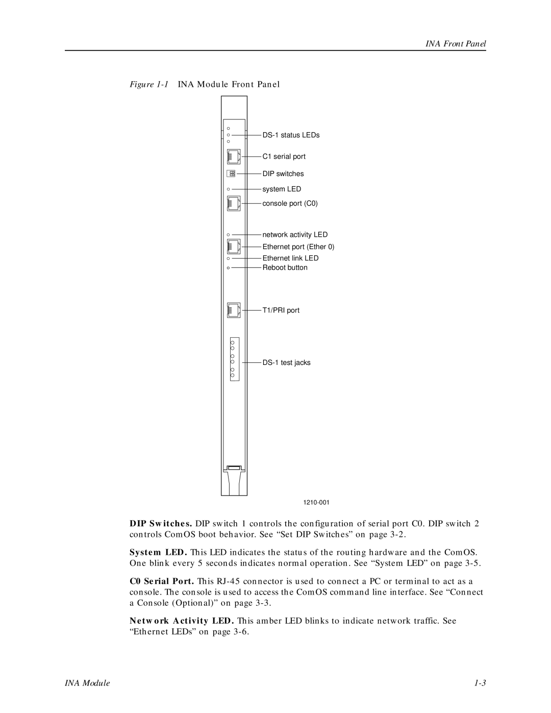
Figure 1-1 INA Module Front Panel
![]()
![]()
![]() C1 serial port
C1 serial port
![]()
![]()
![]()
![]() DIP switches system LED
DIP switches system LED ![]()
![]() console port (C0)
console port (C0)
network activity LED
![]()
![]()
![]() Ethernet port (Ether 0)
Ethernet port (Ether 0)
Ethernet link LED ![]()
![]() Reboot button
Reboot button
![]()
![]()
![]() T1/PRI port
T1/PRI port
DIP Switches. DIP switch 1 controls the configuration of serial port C0. DIP switch 2 controls ComOS boot behavior. See “Set DIP Switches” on page
System LED. This LED indicates the status of the routing hardware and the ComOS. One blink every 5 seconds indicates normal operation. See “System LED” on page
C0 Serial Port. This
Network Activity LED. This amber LED blinks to indicate network traffic. See “Ethernet LEDs” on page
INA Module |