Processes
OM-196 188K
Description
From Miller to You
Table of Contents
100
Introduction to Programming
101
Setup
Control Menu
Directives
Standards
Symbol Usage
Marks a special safety message
Arc Welding Hazards
Electric Shock can kill
ARC Rays can burn eyes and skin
Welding can cause fire or explo- sion
Flying Metal can injure eyes
Buildup of GAS can injure or kill
Principal Safety Standards
EMF Information
About Pacemakers
Signification des symboles
Consignes DE Securite Lire Avant Utilisation
UN Choc Électrique peut tuer
LES Fumées ET LES GAZ peuvent être dangereux
LE Soudage peut provoquer un incendie ou une explosion
DES Particules Volantes peuvent blesser les yeux
DES Pièces Chaudes peuvent pro- voquer des brûlures graves
LE Bruit peut affecter l’ouïe
Risque D’INCENDIE OU
LA Chute DE L’APPAREIL peut blesser
’EMPLOI Excessif peut
DES Organes Mobiles peuvent provoquer des blessures
Information sur les champs électromagnétiques
Principales normes de sécurité
Consignes relatives aux stimulateurs cardiaques
Definitions
Manufacturer’s Warning Label Definitions
∠ =
60 s
Symbols And Definitions
Manufacturer’s Rating Label
Harmonic Data
Harmonic Data per IEC 61000-3-12, draft
Specifications
Installation
Dimensions And Weight
Connection Diagram
Selecting a Location
Movement Location
Tipping
Weld Output Terminals And Selecting Cable Sizes
Volts AC Duplex Receptacle And Circuit Breakers
10 100% Duty Cycle
Duty Cycle
Electrical Service Guide
Connecting Input Power
Three-Phase
Always connect grounding conductor first
Rear Panel Connections
Example Receptacle
Peripheral Receptacle Functions
Socket Information
Touch Sensor Board PC18 Switch S1 Settings
Touch Sensor Operation
Top View
Front
Connecting Setup Pendant To Welding Power Source
Turn Off welding power source and weld control
Operation
Operational Terms
Lower Front Panel Controls
Meter Functions
Upper Front Panel Controls
Volt-Ampere Curves
Duty Cycle And Overheating
Overheating
Setup Pendant Controls
Increase Button
Maintenance & Troubleshooting
Routine Maintenance
Blowing Out Inside Of Unit
Months
Removing Case and Measuring Input Capacitor Voltage
Voltmeter/Ammeter Help Displays
Help 1 Display
Front Panel Error Displays
Weld Interface Board PC12 Diagnostic LED’s
LED2 LED4 LED8 LED10 LED11 LED6 LED3 LED5 LED7 LED9 LED12
Diagnostic LED’s On Weld Interface Board PC12
Status Diagnosis
Customer Interface Board PC14 Diagnostic LED’s
Diagnostic LED’s On Customer Interface Board PC14
Motor Board PC13 Diagnostic LED’s
Troubleshooting
Diagnostic LED’s On Motor Board PC13
Trouble Remedy
OM-196 188
Electrical Diagrams
Circuit Diagram For Welding Power Source
203 505-A
Circuit Diagram For Control Board PC1 Part 1
203 311 1
Circuit Diagram For Control Board PC1 Part 2
203 311 2
Circuit Diagram For Control Board PC1 Part 3
203 311 3
Circuit Diagram For Function/Meter Board PC3
190
Circuit Diagram For Interconnect Board PC2
OM-196 188
Circuit Diagram For Interface Module
193 709-A
Circuit Diagram For Microprocessor Board PC11
191
10. Circuit Diagram For Motor Board PC13
212 354-A
11. Circuit Diagram For Switch Board PC15
12. Circuit Diagram For Junction Board PC16
13. Circuit Diagram For Interface Board PC12 Part 1
191 843-A Part 1
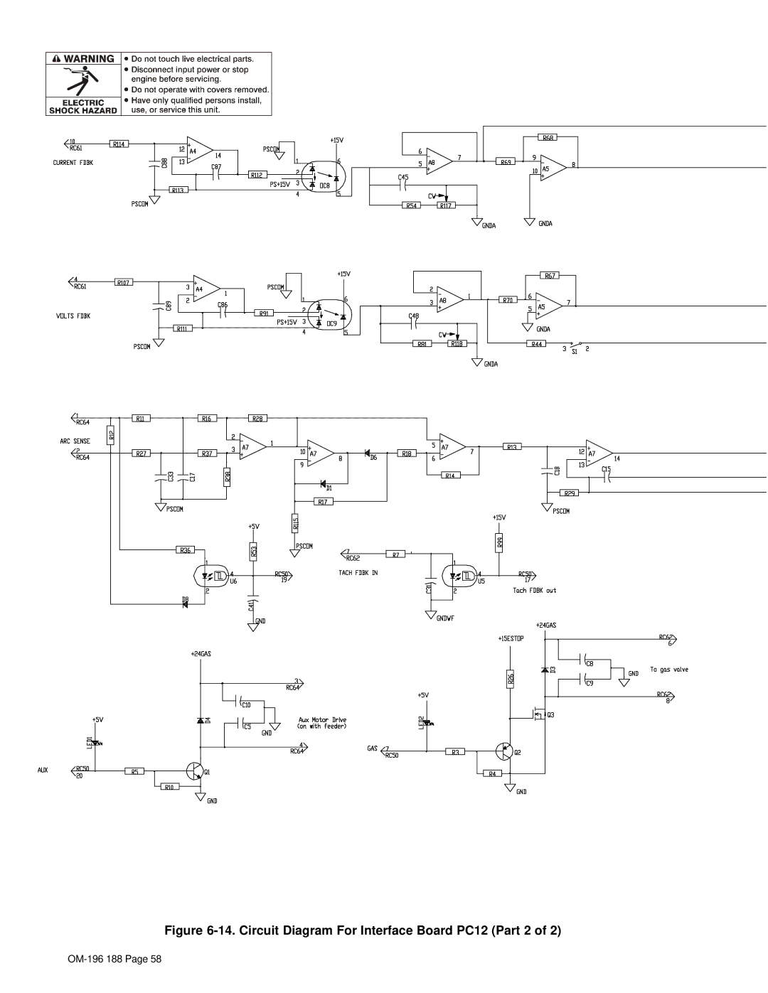
14. Circuit Diagram For Interface Board PC12 Part 2
191 843-A Part 2
15. Circuit Diagram For Customer Interface Board PC14 Part 1
Pensar 86147s03 Part 1
16. Circuit Diagram For Customer Interface Board PC14 Part 2
Pensar 86147s03 Part 2
17. Circuit Diagram For Customer Interface Board PC14 Part 3
Pensar 86147s03 Part 3
18. Circuit Diagram For Touch Sensor Board PC18
19. Circuit Diagram For Setup Pendant
200
21. Circuit Diagram For Power Distribution Board PC20
Parts List
Complete Assembly
PLG21
RC10
194 Setup Pendant
Optional
OM-196 188
Programming Instructions for
Program Hardwire Selected Softwire Selected
Introduction to Programming
Pulse MIG Programs
Standard Pulse Welding Programs
Program 1 1.2 mm Steel .045, 98-2 Argon-Oxy
Program 2 1.0 mm Steel .040, 80-20 Argon-CO2
Program 4 .8 mm 316 .030, 98-2 Argon-CO2
Program 3 1.2 mm Steel .045, 80-20 Argon-CO2
Gas Ar CO2 / 19 L/min 40 CFH
Program 5 1.0 mm 316 .040, 98-2 Argon-CO2
Program 6 1.2 mm 316 .045, 98-2 Argon-CO2
Program 7 1.0 mm 308L .040, 98-2 Argon-CO2
Program 8 1.2 mm 308L .045, 98-2 Argon-CO2
Program 1 1.2 mm Metal Core .045, 95-5 Argon-CO2
Program 2 1.4 mm Metal Core .052, 95-5 Argon-CO2
Wire Size/Type 1.2 mm .045 ER Gas Ar / 19 L/min 40 CFH
Wire Size/Type 1.0 mm .040 ER Gas Ar / 19 L/min 40 CFH
Program 3 1.2 mm ER 4043 .045, Argon
Program 4 1.0 mm ER 4043 .040, Argon
Program 5 1.0 mm 5356 .040, Argon
Program 6 1.2 mm ER 5356 .045, Argon
Program 8 1.0 mm Steel .040, 98-2 Argon-Oxy
Program 7 .8 mm Steel .030, 98-2 Argon-Oxy
Gas Ar Oxy/ 19 L/min 40 CFH
Setup Pendant Mode Select Button
Setup Pendant Parameter Select Button
Setup Pendant Parameter Increase And Decrease Buttons
Getting Started for Pulse Welding
Setting Preflow Sequence Display
Weld Cycle For Pulse Welding
Setting Weld Sequence Display
Setting Crater Sequence Display
Teaching a Pulse Welding Program
Setting Postflow Sequence Display
Pulse Waveform Explained
Teach Points Explained
IPM
Page
Setting Teach Point Parameters For Pulse Welding Program
Wire Size/Type Gas
Card # Gun Model Flowrate
PWms Vpk
Sec Run-In Trim
Changing To Adaptive Pulse Welding
Teaching a MIG Welding Program
Weld Cycle For Mig Welding
Changing To Mig Welding
Setting Start Sequence Display
Setting Retract Sequence Display
Setting Run-in Sequence Display
Poflw Sec Parameter Select Postflow Parameters Display
Setting SharpArcE Control
Selecting And Adjusting SharpArcE Control
Using the Optional Data Card
Installing Data Card
Using The Data Card
Naming Programs And Writing To Card
Yes
Reading From Card
Reading Or Deleting From An Empty Card
Deleting Programs From Card
Security lock works only when a data card is inserted
Selecting Security Lock
Setup
Setup Flow Chart
Features Settings Default Section
Display Features Settings Default
Using Setup Displays
T u p
Selecting Or Changing Access Code
ZWX
Selecting Auxiliary Output
Selecting Voltage Correction
Selecting Voltage Sensing Method
Resetting Arc Time
Selecting Arc Start Method
Selecting Units For Wire Feed Speed And Motor Type
Selecting Wire Type
Defining Display Value
Resetting Memory
Selecting Arc Start/Volt Sense Error Shutdown
Selecting Program Name Feature
Remote Program Setting
Remote Program Select
Program No Output a Output B Output C
Jog Wire Feed Speed Selection
Flow Selection
Arc Voltage Error Selection
Stick Check Selection
Exiting The Setup Menu
Setting Ramps Function
Software Version Number
Using Menu Display
Control Menu
Setting Rise Time Parameter
Setting Adaptive Parameters
Setting Auto Configure Parameter
Setting Retract On/Off
Setting Sharp Start On/Off
Exiting The Control Menu
Page
Service
Support
Owner’s Record
Miller Electric Mfg. Co