Specifications
Rated Power Supply:
Rated Input:
Color System:
Operating Temperature:
Relative Humidity:
Altitude:
Dimensions:
Weight:
Recording System
Sampling
Data Compression
Compression Unit
Resolution
Recording Device
Video Input:
Monitor Output:
Throughout Output:
Timer Program:
Memory Backup:
CONNECTORS
POWER ON Input:
POWER OFF Input:
ALARM
CLOCK ADJ Input:
REC Input:
GND:
ALARM OUT Output:
MODE OUT Output:
DC 5V OUT Output:
CALL OUT/CALL OUT GND:
Rating:
ALARM OUT /
MODE OUT
ALARM IN / CLOCK ADJ /
REC
CALL OUT /
CALL OUT GND
SCSI
Accessories
AC power cord (for U.K / for the Continent) Ferrite core
Cable tie
AC
1.0- 0.5A
Max.2000(m)
425(Width) x 380(Depth) x 113(Height)(mm). 7.5kg
Digital recording system with JPEG compression method. 13.5MHz
JPEG
Field
684 x 288 60GB HDD
16 | Input | 1.0 |
|
| |
1.0 | ||
16 | Output | 1.0 |
Terminal for power ON. LOW: POWER OFF / HIGH: POWER ON
Terminal for power OFF. LOW: POWER OFF Terminal for starting alarm recording.
Terminal for adjusting clock.
Terminal for start recording.
Terminal for ground.
Terminal for output while alarm recording is under way. Terminal for indication of recording selected mode. Terminal for DC 5V OUT.
Terminal for external warning device.
Active: | “Low” Level. | Max. Drive current 7mA DC. |
Non active: | Open. | Max. Voltage +24V DC. |
Active: | When terminals are | |
| or “Low” Level voltage is applied. | |
Non active: | Open. |
|
Active: | ON. | Max. Drive current 7mA DC. |
Non active: | Open. | Max. Voltage +24V DC. |
2
3
3
ENGLISH |
Weight and dimensions shown are approximate.
Design and specifications are subject to change without notice.
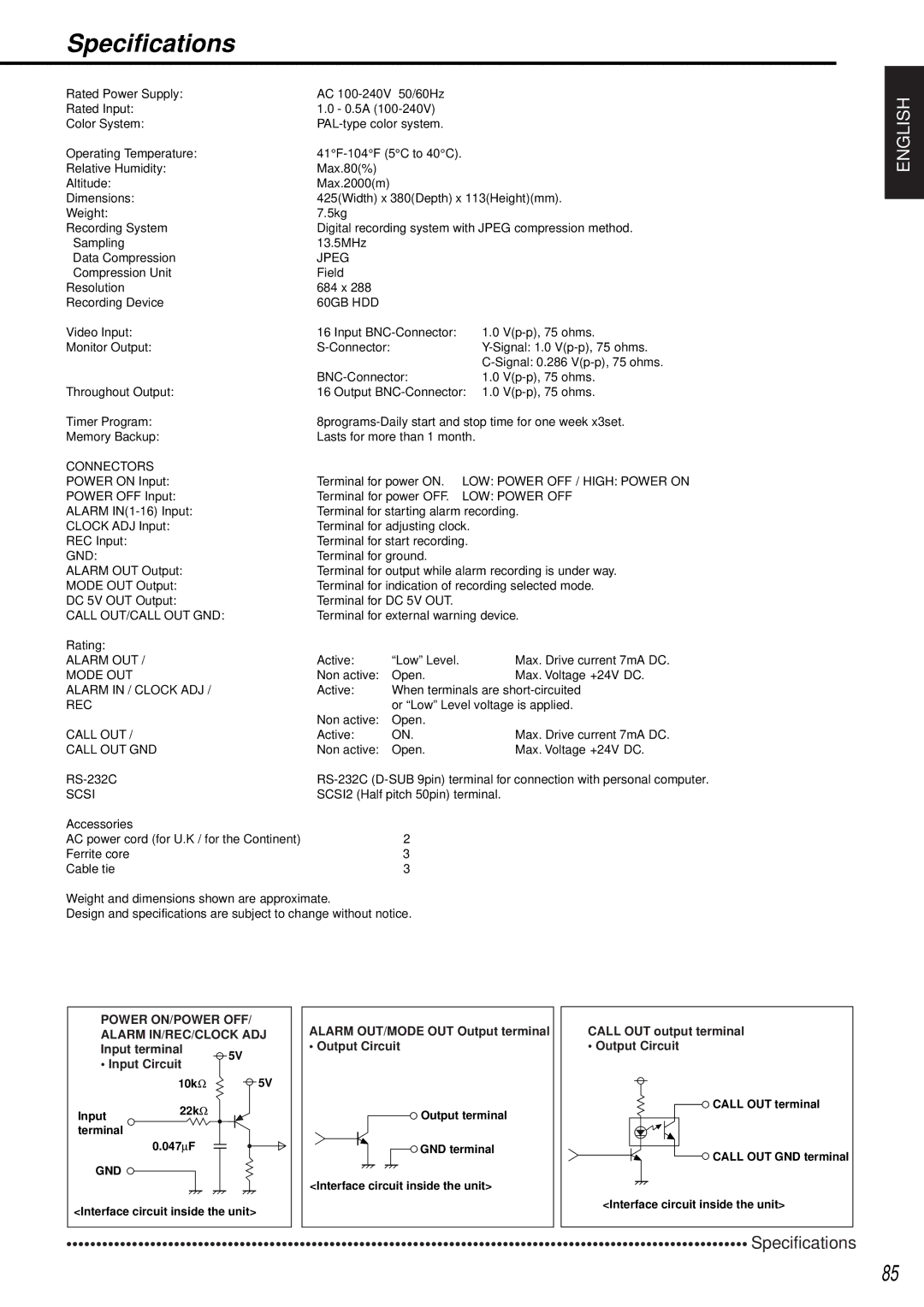
POWER ON/POWER OFF/ ALARM IN/REC/CLOCK ADJ Input terminal
ALARM OUT/MODE OUT Output terminal
• Output Circuit
CALL OUT output terminal
• Output Circuit
• Input Circuit
5V
10kΩ5V
Input22kΩ terminal
0.047∝F
GND
<Interface circuit inside the unit>
Output terminal
GND terminal
<Interface circuit inside the unit>
CALL OUT terminal
CALL OUT GND terminal
<Interface circuit inside the unit>
••••••••••••••••••••••••••••••••••••••••••••••••••••••••••••••••••••••••••••••••••••••••••••••••••••••••••••••••••Specifications
85