Memory Maps
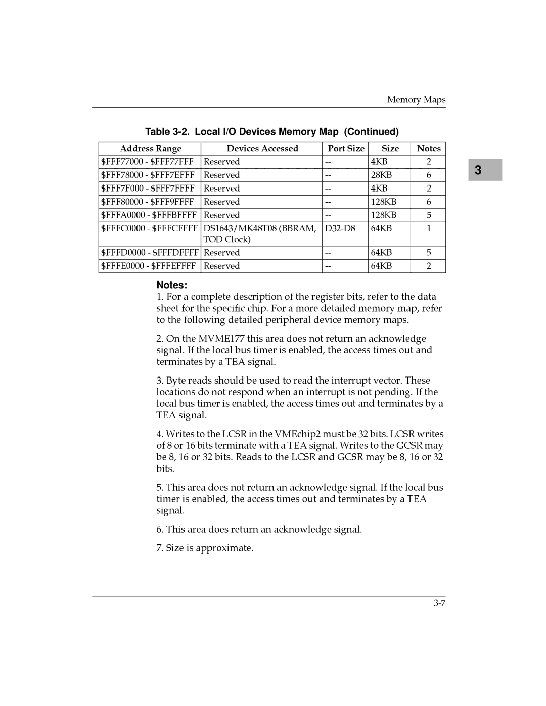
Table 3-2. Local I/O Devices Memory Map (Continued)
Address Range | Devices Accessed | Port Size | Size | Notes |
|
|
|
|
|
$FFF77000 - $FFF77FFF | Reserved | 4KB | 2 | |
|
|
|
|
|
$FFF78000 - $FFF7EFFF | Reserved | 28KB | 6 | |
|
|
|
|
|
$FFF7F000 - $FFF7FFFF | Reserved | 4KB | 2 | |
|
|
|
|
|
$FFF80000 - $FFF9FFFF | Reserved | 128KB | 6 | |
|
|
|
|
|
$FFFA0000 - $FFFBFFFF | Reserved | 128KB | 5 | |
|
|
|
|
|
$FFFC0000 - $FFFCFFFF | DS1643/MK48T08 (BBRAM, | 64KB | 1 | |
| TOD Clock) |
|
|
|
|
|
|
|
|
$FFFD0000 - $FFFDFFFF | Reserved | 64KB | 5 | |
|
|
|
|
|
$FFFE0000 - $FFFEFFFF | Reserved | 64KB | 2 | |
|
|
|
|
|
Notes:
1.For a complete description of the register bits, refer to the data sheet for the specific chip. For a more detailed memory map, refer to the following detailed peripheral device memory maps.
2.On the MVME177 this area does not return an acknowledge signal. If the local bus timer is enabled, the access times out and terminates by a TEA signal.
3.Byte reads should be used to read the interrupt vector. These locations do not respond when an interrupt is not pending. If the local bus timer is enabled, the access times out and terminates by a TEA signal.
4.Writes to the LCSR in the VMEchip2 must be 32 bits. LCSR writes of 8 or 16 bits terminate with a TEA signal. Writes to the GCSR may be 8, 16 or 32 bits. Reads to the LCSR and GCSR may be 8, 16 or 32 bits.
5.This area does not return an acknowledge signal. If the local bus timer is enabled, the access times out and terminates by a TEA signal.
6.This area does return an acknowledge signal.
7.Size is approximate.
3 |