Memory Maps
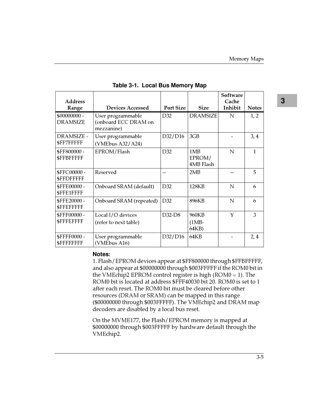
Table 3-1. Local Bus Memory Map
|
|
|
| Software |
|
Address |
|
|
| Cache |
|
Range | Devices Accessed | Port Size | Size | Inhibit | Notes |
$00000000 - | User programmable | D32 | DRAMSIZE | N | 1, 2 |
DRAMSIZE | (onboard ECC DRAM on |
|
|
|
|
| mezzanine) |
|
|
|
|
DRAMSIZE - | User programmable | D32/D16 | 3GB | - | 3, 4 |
$FF7FFFFF | (VMEbus A32/A24) |
|
|
|
|
|
|
|
|
|
|
$FF800000 - | EPROM/Flash | D32 | 1MB | N | 1 |
$FFBFFFFF |
|
| EPROM/ |
|
|
|
|
| 4MB Flash |
|
|
|
|
|
|
|
|
$FFC00000 - | Reserved | 2MB | 5 | ||
$FFDFFFFF |
|
|
|
|
|
|
|
|
|
|
|
$FFE00000 - | Onboard SRAM (default) | D32 | 128KB | N | 6 |
$FFE1FFFF |
|
|
|
|
|
|
|
|
|
|
|
$FFE20000 - | Onboard SRAM (repeated) | D32 | 896KB | N | 6 |
$FFEFFFFF |
|
|
|
|
|
|
|
|
|
|
|
$FFF00000 - | Local I/O devices | 960KB | Y | 3 | |
$FFFEFFFF | (refer to next table) |
| (1MB- |
|
|
|
|
| 64KB) |
|
|
|
|
|
|
|
|
$FFFF0000 - | User programmable | D32/D16 | 64KB | - | 2, 4 |
$FFFFFFFF | (VMEbus A16) |
|
|
|
|
|
|
|
|
|
|
Notes:
1.Flash/EPROM devices appear at $FF800000 through $FFBFFFFF, and also appear at $00000000 through $003FFFFF if the ROM0 bit in the VMEchip2 EPROM control register is high (ROM0 = 1). The ROM0 bit is located at address $FFF40030 bit 20. ROM0 is set to 1 after each reset. The ROM0 bit must be cleared before other resources (DRAM or SRAM) can be mapped in this range ($00000000 through $003FFFFF). The VMEchip2 and DRAM map decoders are disabled by a local bus reset.
On the MVME177, the Flash/EPROM memory is mapped at $00000000 through $003FFFFF by hardware default through the VMEchip2.
3 |