Netopia R910 Ethernet Router status lights
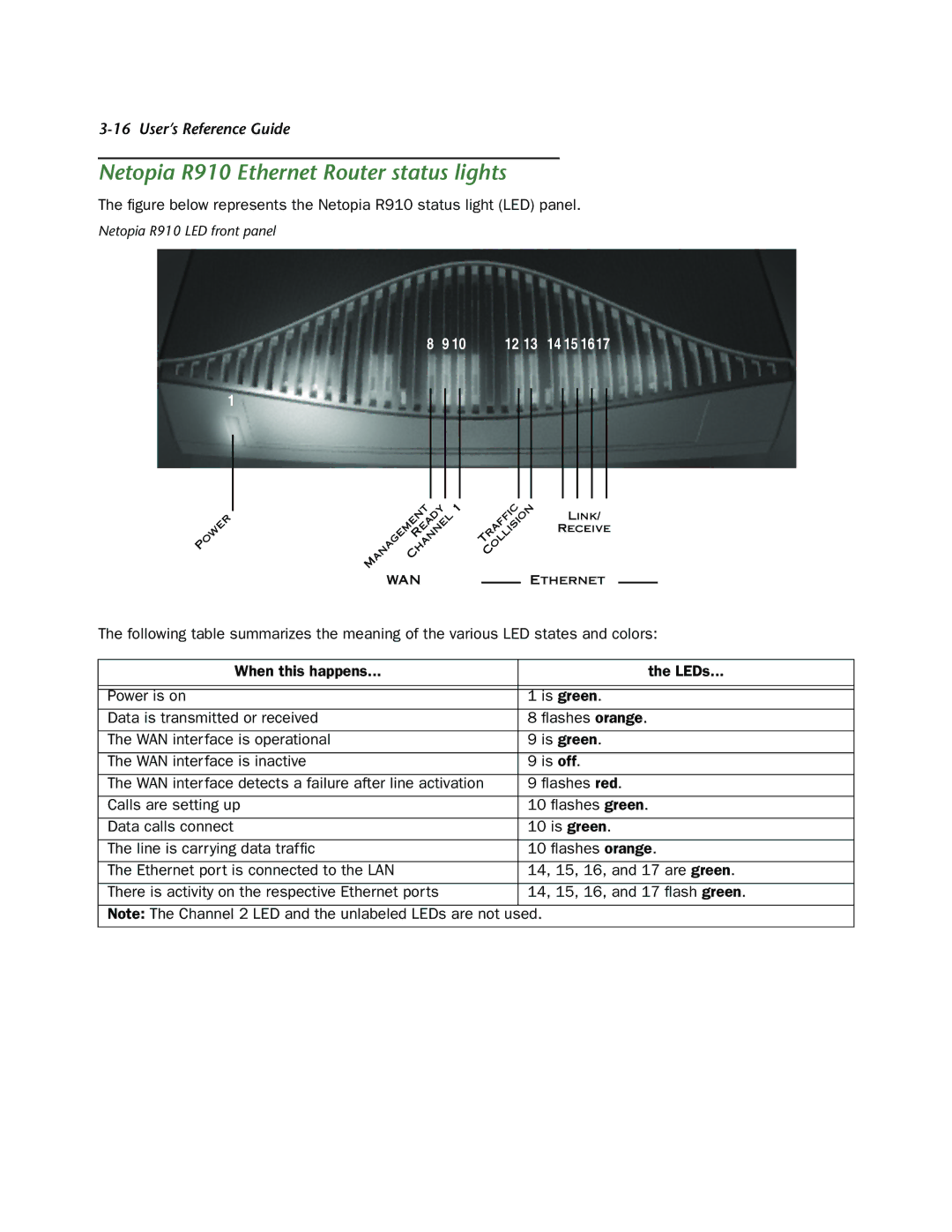
The figure below represents the Netopia R910 status light (LED) panel.
Netopia R910 LED front panel
8 9 10 12 13 14 15 16 17
1
P | OWER |
|
| ANAGEMENT | 1 | ||
|
| |||
|
|
| EADY |
|
|
| HANNEL |
| |
| R |
|
| |
M | C |
|
|
|
|
|
|
| |
WAN
| C |
|
T OLLISION | LINK/ | |
fi |
| |
RAF |
| RECEIVE |
|
| |
C |
|
|
ETHERNET
The following table summarizes the meaning of the various LED states and colors:
When this happens... | the LEDs... |
|
|
|
|
Power is on | 1 is green. |
Data is transmitted or received | 8 flashes orange. |
|
|
The WAN interface is operational | 9 is green. |
|
|
The WAN interface is inactive | 9 is off. |
|
|
The WAN interface detects a failure after line activation | 9 flashes red. |
|
|
Calls are setting up | 10 flashes green. |
|
|
Data calls connect | 10 is green. |
|
|
The line is carrying data traffic | 10 flashes orange. |
|
|
The Ethernet port is connected to the LAN | 14, 15, 16, and 17 are green. |
|
|
There is activity on the respective Ethernet ports | 14, 15, 16, and 17 flash green. |
|
|
Note: The Channel 2 LED and the unlabeled LEDs are not used.