User’s Guide
Adept SmartController
Page
00356-00100, Rev. E May
Page
Table of Contents
SmartController Operation
Table of Contents
SmartController Maintenance
SDIO Module
Using the Manual Control Pendant MCP 125
Index
Figure A-1
List of Figures
List of Figures
List of Tables
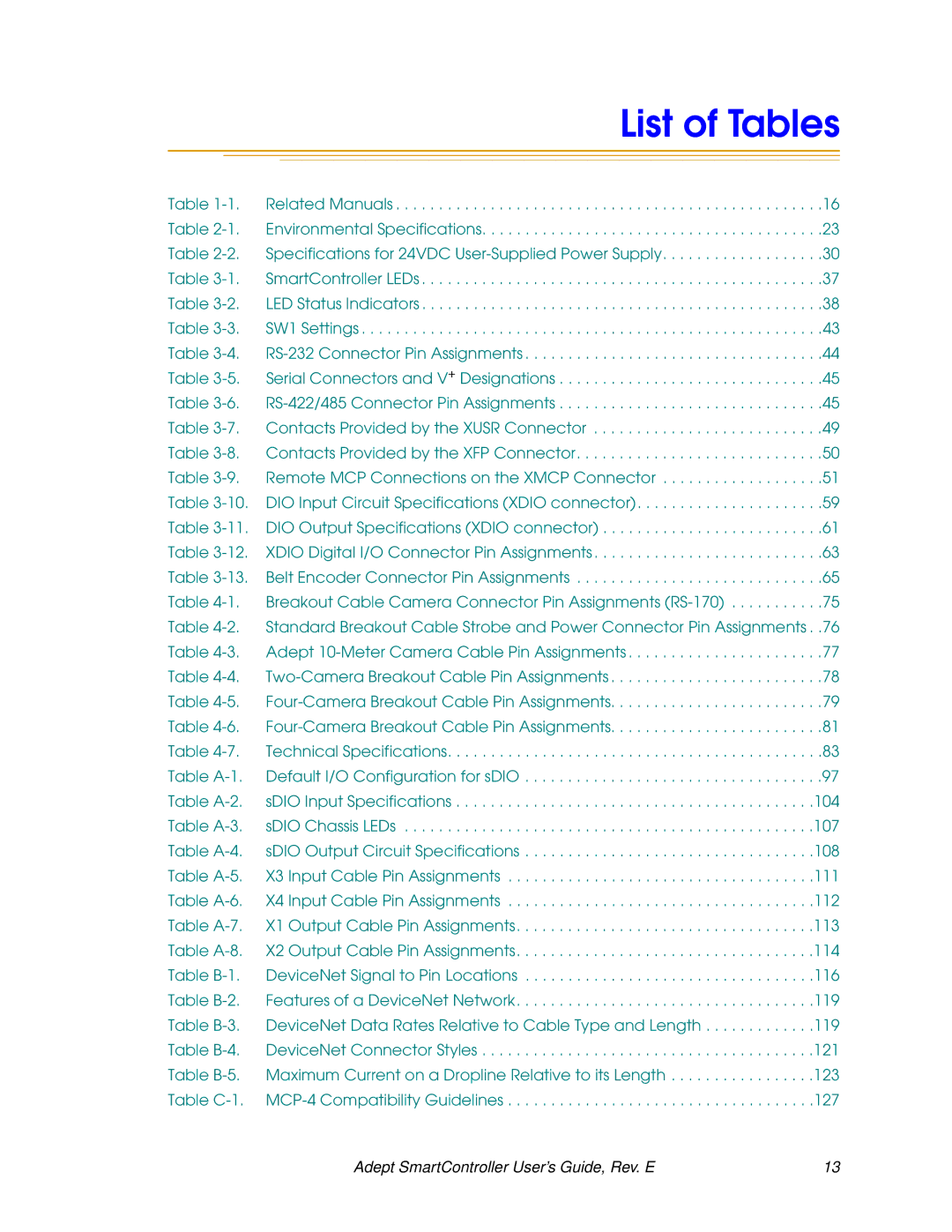
List of Tables
Product Description
Introduction
Adept SmartController CS
Adept SmartController CX
Related Manuals
How Can I Get Help?
Adept Document Library
Introduction
Reading and Training for Users and Operators
Safety
Safety Features on the Front Panel
System Safeguards
Computer Controlled Robots and Motion Devices
Program Security
Safety
Manually Controlled Robots and Motion Devices
Other Computer-Controlled Devices
Inappropriate Uses of the Adept SmartController
Standards Compliance
Identification
CAT-3 Version of SmartController
Functionality Changes
Stop Circuit
Operational Change in SmartModule Systems
Controller Installation
SmartController Installation
Before Unpacking
Upon Unpacking
Repacking for Relocation
SmartController Installation
Space Around the Chassis
Mounting the SmartController
Rack Mounting the SmartController
Controller Installation
Panel Mounting the SmartController
Panel Mounting the SmartController
Table Mounting the SmartController
Table Mounting the SmartController
CompactFlash Memory Card
Stacking Components
CompactFlash Memory Card Compartment
Installing CompactFlash
24VDC Power Specifications
Connecting Power
Daisy-Chaining Power
24VDC Power Cabling
Grounding
Grounding Point
Installing 24VDC Connectors
V Connectors
Ieee 1394 Cable Specifications
PDU2
System Cable Installation
System Cable Installation
Page
SmartController Operation
SmartController CS Connectors and Indicators
Top Three Status LEDs
Green Indicates Red Indicates
SW1 DIP switches
LED Display Error # Description
DeviceNet connector
Bottom Three Status LEDs
RS-232 and RS-422/485 connectors
Ethernet Eth 10/100 connector
Xdio connector
Xusr connector
SmartController CX Connectors and Indicators
Manual/Automatic Mode Switch
System 5V Power On LED
High Power On/Off Switch & Lamp
Front Panel
Factory Default Settings
Configuring the Controller
DIP-Switch Settings
Emergency Stop Switch
Row # Interpretation
Configuring the Controller
AdeptWindows PC Graphical User Interface
Ascii Terminal
RS-232 Connectors
SmartController Serial I/O Connectors
Auto Boot
Pin Signal Type
SmartController Serial I/O Connectors
RS-422/485 Connector
Controller Connector + Designation
Graphical Interface Using AdeptWindows
Installing the User Interface
Installing the User Interface
Text Interface Using a PC with HyperTerminal Software
Installation Procedure
Start = Programs = Accessories = HyperTerminal
Recommended Terminal for Text-Based Systems
Text Interface Using a Terminal
Pin Description Comments Shorted if Pairs Not Used
Connecting Equipment to the System
Description Comments
Pin Pairs
Pin Xmcp Pin MCP Description Pin D-Sub Pin CPC
CAT-3 E-Stop Circuit on Xusr and XFP Connectors
Stop, High Power On/Off and MANUAL/AUTO Controls
Emergency Stop Circuits
Adept Front Panel Schematic
User E-Stop Indication Remote Sensing of E-Stop
Muted Safety Gate E-Stop Circuitry
Line E-Stop Input
User High Power On Indication
Remote Manual Mode
High Power On/Off Lamp
Remote High Power On/Off Control
Remote Front Panel Usage
Remote MCP Usage
Connecting Customer-Supplied Digital I/O Equipment
Connecting Customer-Supplied Digital I/O Equipment
Xdio Connector
Input Signals
Fast Input Signals 1001 to
React Input Signals 1001 to
11. DIO Output Specifications Xdio connector
Output Signals
Digital Output Wiring for Xdio Connector
Pin Signal
Screw-Terminal Field-Wiring Adapter Blocks
Digital I/O Connector Ordering Details Third-Party Sources
Belt Encoder Interface on SmartController CX
Channel Signal Pin
Belt Encoder Interface on SmartController CX
Belt Encoder Typical Input Circuit
AdeptVision sAVI Option
SAVI Board Features
Introduction
SAVI Board System Requirements and Restrictions
Pixel Format
Camera Compatibility
AdeptVision sAVI Inspection System Limitations
Guidelines for Cameras
High Resolution Cameras
Standard Resolution Cameras
Cameras Supported
Camera Compatibility
Two-Camera Breakout Cable for RS-170 Cameras
Camera Cables
Meter Camera Extension Cables
Four-Camera Breakout Cable for RS-170 Cameras
Camera Cables
Connecting the Cables to the RS-170 Standard Camera
Installing Camera Cables
Camera Cable Installation Drawing RS-170
Installing Camera Cables
Camera Cable Pin and Signal Information
Pin Function
Camera Cable Pin and Signal Information
Pin Function
Pin Locations for Camera Cable Connector 12-Pin Hirose Male
From Pin Function
From Pin Function
Str/Pwr User +12 V to cameras User power return
Pin
Pin
SAVI Board Specifications
SAVI Board Specifications
Page
Changing the Lamp in the High Power Indicator
SmartController Maintenance
Lamp Body Contact Alignment
SmartController Maintenance
SmartController Dimensions
Technical Specifications
Technical Specifications
SDIO Dimensions
Adept Front Panel Dimensions
Adept Front Panel Dimensions
Adept Front Panel Back View
Adept MCP Dimensions
Adept MCP Dimensions
MCP Cradle Dimensions
Mounting the sDIO
SDIO Module a
Appendix a sDIO Module
Rack Mounting the sDIO
Mounting the sDIO
Panel Mounting the sDIO
Table Mounting the sDIO
Installing the sDIO
Stack Mounting
Default sDIO I/O Configuration
Configuring a Single sDIO
Configuring a Single sDIO
Input Signal Block Byte Output Signal Numbers
Assigning sDIO Signal Blocks
Modifying the Default sDIO Configuration
Configure 1394 DIO
+ System Configuration Data Then, press Enter to continue
Assigning I/O Signal Numbers
Enter new value
Do you want to save these changes?
100 Adept SmartController User’s Guide, Rev. E
Edit system configuration Then, press Enter to continue
Adept SmartController User’s Guide, Rev. E 101
SDIO Signal Mapping Example
102 Adept SmartController User’s Guide, Rev. E
Using Multiple sDIO Modules
Configuring a System with an sDIO and a RIO
SDIO Module Connectors and Indicators
SDIO Module Connectors and Indicators
Status LEDs
SDIO Inputs
SDIO Digital I/O Signals
104 Adept SmartController User’s Guide, Rev. E
Adept SmartController User’s Guide, Rev. E 105
SDIO Digital I/O Signals
SDIO Outputs
Testing sDIO Outputs
SDIO LEDs
106 Adept SmartController User’s Guide, Rev. E
Illumination Upper LED Link Lower LED OK SF
SDIO Output Power Supply Current Selection
Adept SmartController User’s Guide, Rev. E 107
108 Adept SmartController User’s Guide, Rev. E
Parameter Value
Adept SmartController User’s Guide, Rev. E 109
Smart-DIO
Labeling Cables
Optional DIO Cables
110 Adept SmartController User’s Guide, Rev. E
Pin Signal Wire Number Group Color Locations
Input and Output Cable Wiring Information
Adept SmartController User’s Guide, Rev. E 111
112 Adept SmartController User’s Guide, Rev. E
Adept SmartController User’s Guide, Rev. E 113
Pin Group Signal name Wire Number Color Pin Locations
114 Adept SmartController User’s Guide, Rev. E
Volume
DeviceNet Specifications
Adept DeviceNet B
Adept SmartController User’s Guide, Rev. E 115
Limitations of the Adept DeviceNet Scanner
Pin Signal Name
Adept Supplied DeviceNet Hardware
Appendix B Adept DeviceNet
DeviceNet Physical Layer and Media
DeviceNet Physical Layer and Media
Adept SmartController User’s Guide, Rev. E 117
118 Adept SmartController User’s Guide, Rev. E
Adept SmartController User’s Guide, Rev. E 119
Data Rates Kbps
120 Adept SmartController User’s Guide, Rev. E
Figure B-2. DeviceNet Thick Cable
Connector Description
DeviceNet Connectors
Termination of the DeviceNet Network
Adept SmartController User’s Guide, Rev. E 121
Power Capabilities of a DeviceNet Cable System
Power Supply and the DeviceNet Bus
122 Adept SmartController User’s Guide, Rev. E
Adept SmartController User’s Guide, Rev. E 123
Length of Dropline Maximum Current
124 Adept SmartController User’s Guide, Rev. E
Figure B-6. DeviceNet Connector Pinouts
MCP Enable Switch Function on CAT-3 SmartController
Using the Manual C Control Pendant MCP
Manual Control Pendant Basics
Adept SmartController User’s Guide, Rev. E 125
Position Enable Switch
Appendix C Using the Manual Control Pendant MCP
126 Adept SmartController User’s Guide, Rev. E
MCP-4 Compatibility
Manual Control Pendant Basics
Adept SmartController User’s Guide, Rev. E 127
CMD
128 Adept SmartController User’s Guide, Rev. E
Adept SmartController User’s Guide, Rev. E 129
Connecting the MCP
Soft Buttons
MCP Layout
Function Buttons
130 Adept SmartController User’s Guide, Rev. E
Emergency Stop From the MCP
Mode Control and Joint/Axis Control Buttons
Data Entry Buttons
Speed Bars and Slow Button
Original SmartController
Re-Enabling Power After Enable Switch Released
CAT-3 SmartController
132 Adept SmartController User’s Guide, Rev. E
MCP Predefined Functions
Background Mode
Introduction
Predefined Function Buttons
134 Adept SmartController User’s Guide, Rev. E
Edit Function
Adept SmartController User’s Guide, Rev. E 135
Display Function
136 Adept SmartController User’s Guide, Rev. E
CMD Function
Clear Error Function
Adept SmartController User’s Guide, Rev. E 137
138 Adept SmartController User’s Guide, Rev. E
Figure C-10. Command CMD Function Button
Adept SmartController User’s Guide, Rev. E 139
Prog Set Function
Moving a Robot or Motion Device With the MCP
Mode Control Buttons
140 Adept SmartController User’s Guide, Rev. E
Moving a Robot or Motion Device With the MCP
Emergency Stop Switch
COMP/PWR Button
MAN/HALT Button
Speed Bars
Joint/Axis Control Buttons
142 Adept SmartController User’s Guide, Rev. E
Slow Button
Comp Mode
Robot States
World State
144 Adept SmartController User’s Guide, Rev. E
Tool State
Adept SmartController User’s Guide, Rev. E 145
+RZ
146 Adept SmartController User’s Guide, Rev. E
Figure C-16. Tool State Six-Axis Robot
Adept SmartController User’s Guide, Rev. E 147
Joint State
148 Adept SmartController User’s Guide, Rev. E
Free State
Adept SmartController User’s Guide, Rev. E 149
Controlling More Than One Robot
Robots With Fewer Than Six Joints
DEV LED state Robot selected by pendant
Robots With More Than Six Joints
Joint/Axis LED state Joint range
Adept SmartController User’s Guide, Rev. E 151
Index
152 Adept SmartController User’s Guide, Rev. E
Index
Adept SmartController User’s Guide, Rev. E 153
143
154 Adept SmartController User’s Guide, Rev. E
Page
Triad Drive