PR-SC886
Important Safety Instructions
Power
Precautions
Preventing Hearing Loss Caution
Batteries and Heat Exposure Warning
For British models
Precautions
Contents
Processing
Features
Connections
Miscellaneous
Make sure you have the following accessories
Supplied Accessories
THX Ultra2 Plus
Main Room
Multiroom Capability
Zone 2 Room Zone 3 Room
Left and right Stereo speakers
Front Panel
Front & Rear Panels
Bn bo bp bq br bs bt ck cl cm cn co Cr cs ct
Front & Rear Panels
Dkbt
Display
Rear Panel
Remote Control
Bk bm bo Cn co Cp cq Crcs
RS232
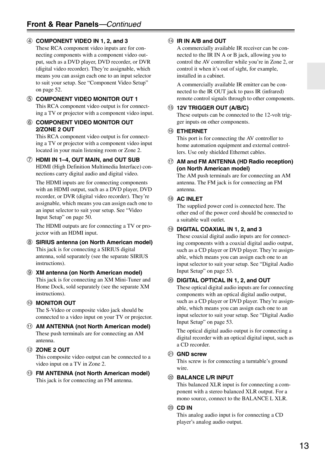
Component Video Monitor OUT
Component Video in 1, 2,
Component Video Monitor OUT 2/ZONE 2 OUT
Hdmi in 1-4, OUT MAIN, and OUT SUB
AUX 1
Tape IN/OUT
GAME/TV
Cr CBL/SAT
Installing the Batteries
Remote Controller
Aiming the Remote Controller
About the Remote Controller Modes
Remote Controller
RECEIVER/TAPE Mode
Remote Mode buttons
Listening Mode buttons
Tape mode
Standby button
DVD Mode
CD/MD/CDR Modes
Dock Mode
Enjoying Home Theater
About Home Theater
Front left and right speakers
Surround back left and right speakers
Connecting Your Speakers
Connecting the AV Controller
Speaker Configuration
Using Dipole Speakers
Connecting a Power Amplifier with RCA Inputs
Connecting the AV Controller
Connecting a Powered Subwoofer
AV controller Multichannel
Speaker Impedance
Connecting a Power Amplifier with XLR Inputs
AV controller
Bi-amping the Front Speakers
Connecting the Indoor FM Antenna
Connecting Antenna
Connecting the AM Loop Antenna
Connecting an Outdoor FM Antenna
Connecting an Outdoor AM Antenna
Using a TV/FM Antenna Splitter
Optical Digital Jacks
About AV Connections
AV Connection Color Coding
AV Cables and Jacks
104, and the Resolution setting to Through see
Connecting Both Audio & Video
Monitor Out Setting Set to Hdmi Main or Hdmi Sub
Which Connections Should I Use?
Video Signal Flow and the Resolution Setting
Monitor Out Setting Set to Analog
Audio Connection Formats
Video Connection
Connecting a TV or Projector
Audio Connection
Hint
DVD player
Connecting a DVD player
Hooking Up the Multichannel Input
DVD recorder
Connecting a VCR or DVD Recorder for Playback
Connecting a VCR or DVD Recorder for Recording
Satellite, cable, set-top box, etc
Digital Optical in 2 CD
About Hdmi
Connecting Components with Hdmi
Supported Audio Formats
About Copyright Protection
Audio Signals
Video Signals
Making Hdmi Connections
Step
Game Console
Connecting a Game Console
Camcorder, etc
Connecting a Camcorder or Other Device
CD Player or Turntable MM with Built-in Phono Preamp Step
Connecting a CD Player or Turntable
Turntable MM with no Phono Preamp Built-in
Connecting a Balanced Audio Source
Connecting a Cassette, CDR, MiniDisc, or DAT Recorder
Stereo audio source with Balanced XLR output
If Your iPod Supports Video
Connecting an RI Dock
If Your iPod Doesn’t Support Video
If you have an Onkyo DS-A1 RI Dock
Connecting the Power Cord
Connecting Onkyo u Components
Do the automatic speaker setup-this is essential
Set the Power switch to the on position
Turning On the AV Controller
Turning On and Standby
Monitor Setup
First Time Setup
Press the Hdmi OUT button
Repeatedly to select
Selecting the Language used for the onscreen setup menus
First Time Setup
Lowed by the Setup button
Using the Onscreen Setup Menus
Menus for First Time Setup
Press the Receiver button fol
Input/Output Assign menu appears
Monitor Out Setup
Monitor Out menu appears
Hdmi Input Setup
Video Input Setup
HDMI1, HDMI2, HDMI3, HDMI4
Hdmi Input menu appears
Tons to select 3. Component
Component Video Setup
Video Input, and then press
Component Video Input menu
Tons to select 1. Input/Output
Digital Audio Input Setup
Assign, and then press Enter
Tons to select 4. Digital Audio
Analog Audio Input menu appears
Analog Audio Input Setup
Stereo
Mono
Tons to select 1. Speaker Set
Speaker Settings
Tings, and then press Enter
TV Format Setup Not North American models
Changing the Input Display
AM Frequency Step Setup on some models
Tons to select 3. Tuner,
Tuner menu appears
Using the Digital Input Button
Automatic Speaker Setup Audyssey MultEQ XT
Measurement Positions
Using Audyssey MultEQ XT
1st measurement position
2nd-8th measurement positions
Setup MIC jack
Place the speaker setup micro
Turn on the AV controller
Connected TV
Disconnect the setup MIC
Speaker Detect Error
Error Messages
Writing Error
Ambient noise is too high
Using a Powered Subwoofer
Changing the Speaker Settings Manually
Reviewing the Results
See Using the Listening Modes on
Select a listening mode and enjoy
Basic Operations
Selecting the Input Source
Adjusting Speaker Levels
Setting the Display Brightness
Basic Operations
Muting the AV Controller
Using Headphones
Using the Sleep Timer
Adjusting the Bass & Treble
Displaying Source Information
Listening to the Radio
Tuning into AM/FM Radio Stations
Listening to AM/FM Stations
Use the Tuner input selector button to select AM or FM
Displaying AM/FM Radio Information
Listening to the Radio
Deleting Presets
Selecting Presets
About HD Radio Stations
Listening to HD Radio Stations North American model only
Selecting Multicast Channels
Selecting the Audio Format Blend Mode
Displaying HD Radio Information
What is RDS?
Using RDS
RDS Program Types PTY
This allows you to search RDS radio stations by type see
Finding Stations by Type PTY
Displaying Radio Text RT
Listening to Traffic News TP
Recording the Input Source
Recording
Recording from Different AV Sources
Selecting with the Remote Controller
Using the Listening Modes
Selecting the Listening Modes
Selecting on the AV Controller
Listening Modes Available for Each Source Format
Using the Listening Modes
Analog and PCM Sources
Requires 6.1/7.1 speakers. Requires 7.1 speakers
Dolby Digital, and Dolby Digital Plus Sources
DTS-ES
DTS Sources
TrueHD Sources
DTS-HD Sources
DSD
DTS Express and DSD Sources
About the Listening Modes
Dolby TrueHD
DTS-HD High Resolution Audio
Channel source + Dolby PLIIx Music
Channel source + Dolby PLIIx Movie
THX Music
THX Cinema
THX Games
THX Ultra2 Cinema
Onkyo Original DSP Modes
Menu Map
Advanced Setup
Submenu Pages
When you’ve finished, press
Advanced Setup
This section explains items on the Input/Output Assign menu
Screen for that item appears
Monitor Out
Speaker Settings
Speaker Setup
Fixed at Full Band if Subwoofer is set to No
Double Bass
Low-Pass Filter for the LFE Channel
Tons to select LPF of LFE,
Tons to select DoubleBass,
Speaker Distance
Speaker Level Calibration
Test tone from each speaker
Repeat until the volume
Is the same
Equalizer Settings
Dynamic EQ
MultEQ XT
Dynamic VolLight
Dynamic VolHeavy
Mode button, followed by
THX Audio Setup
If the main menu doesn’t appear, make
Tons to select 6. THX Audio
Audio Adjust
DSD Setting
Tone Control Settings
Multiplex/Mono Settings
PLIIx/Neo6 Settings
Theater-Dimensional T-D Setting
Dolby EX Settings
LFE Level Settings
100
Using the Re-EQ Function
Using the Music Optimizer
101
Source Setup
Using the Late Night Function
102
103
IntelliVolume
Name Edit
Sync
Game Mode
Picture Adjust
Zoom Mode
ISF Mode
105
Satellite Radio
106
Sirius Parental Lock
107
Listening Mode Presets
Volume Setup
Miscellaneous Setup
108
12V Trigger A/B/C Setup
OSD Setup
109
Remote Control
Hardware Setup
110
Zone2/Zone3
Tuner
111
Analog Multich
112
Network Settings
What’s DHCP?
113
Lock Setup
114
Specifying the Digital Signal Format
Selecting Audio Inputs
Audio SEL
Connecting Your Zone 2 Speakers
Connecting Zone
Zone 2 and Zone
115
116
Connecting Your Zone 3 Speakers
Zone 2 and Zone
Zone 3 speakers must be connected to an amp in Zone
Using Zone 2 and Zone
Zone 2/Zone 3 Out Settings
117
118
Zone 2 or Zone 3 indicator flashes
Selecting an Input Source for Zones Turning Off Zones
Muting Zones
119
When you’ve finished, press the Setup button
Using the 12V Triggers
120
Tons to select 6. Miscellaneous
Using a Multiroom Kit with Zone 2/3
Using a Multiroom Kit with a Cabinet
Using a Multiroom Kit with Other Components
121
Controlling Other Components
Entering Remote Control Codes
122
Remote Control Codes for Onkyo Components Connected via u
Resetting the Remote Controller
Resetting the Remote Mode Buttons
123
124
125
Learning Commands
126
Using Macros
Making Macros
Running Macros
127
Troubleshooting
128
Troubleshooting
129
130
131
Video Resolution Chart
132
Specifications
133
Memo
Onkyo Europe UK Office
Onkyo Europe Electronics GmbH