MN1030 Series Cross Assembler User’s Manual
Page
Page
Manual Features
Reference Techniques
How to read
Heading
Program example
Usage note
Related Manuals
Chapter Writing Macro Control Statements
Purpose of This Chapter Rules of Usage Usage Example
Purpose of This Chapter
Chapter Types of Source Statements
Writing Assembler Control Statements
Readinig List Files
Error Correction Using Tag Jumps 306
Chapter
Purpose of This Chapter
Operating Environment
Host machine Operating system Version of OS
Solaris Or later
98/Me/2000/XP
File Organization
As103 assembler
Ld103 linker
Slib103 library manager
Installation
Start-up files
Setup
Setting command path
Start-up file format
Keywordparameter
Keyword Description
Message
Notation
Option
En-OPTION
Ed-OPTION
Stdlib
Libdir
General command format
File Conversion Utility
Options
Excv103 options EX format file name
Default specification
Rules of output file name
Example of specifying options
Program Development Flow
Program Development Flow
Assembler and compiler
Program Development Flow
Main development flow
Source code debugger
Reference , Using Linker, for details
Programming with Assembler
Required knowledge
Program format
Programming style
Optimization
Debugging
Conditional assembly
Macros
Program Development Flow Programming with Assembler
Introduction to Operation
Introduction to Operation
Files Used by Assembler and Linker
Files Used
Introduction to Operation
Basic Operation of Assembler and Linker
Create source files
Contents of program2.asm are as follows
Assemble
Link
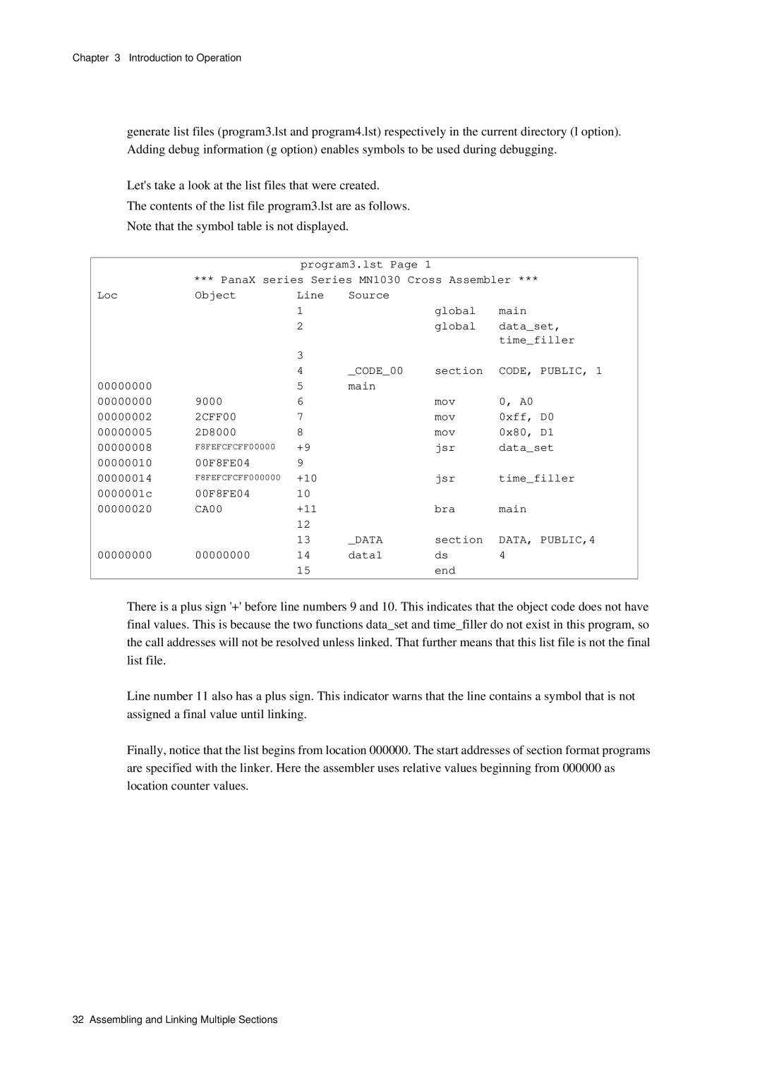
Generate final list files
Contents of the final list file program1.lst are as follows
Contents of the final list file program2.lst are as follows
Assembling and Linking Multiple Sections
Contents of program4.asm are as follows
Assemble and generate list files
DATA, PUBLIC,4
Contents of the list file program4.lst are as follows
Following command was input to link
Parameter file during linking
CAE0 Data
Contents of the final list file program4.lst are as follows
Program locations after linking
Program Location
#ifdef
Conditional Assembly and Linking
Create source file
Assemble and link
Assemble and link the program that you have created
Specify assembly conditions in the command
Select false condition, assemble, and link
As103 -D Debug program5.asm
Introduction to Operation Conditional Assembly and Linking
Chapter Optimization
Has been optimized
Optimization is off by default
Rules of Usage
Usage Example
Optimization Instructions
Optimized Conditional Branch Instructions Type Branch Range
Instruction Type Branch Range
Abs, An
Abs, Dn
An, abs
Dn, abs Movhu abs, Dn Movhu Dn, abs
Btst imm, Dn
Logical Instructions Subject To Optimization
Instruction
Optimization processing
Optimization processing of conditional branch instructions
Assembler processing
Linker processing
BNE*+5
Optimization of function calls
Optimization of branches
BRA label
Label JMP label
Label JMP label Call label Calls label JSR label
Optimization
Optimization
Opt
Text
CA7F
Example subroutine call converted to a relative branch
Using Assembler
Using Asssembler
Specifying options
General format of commands
Starting Assembler
Summary of options
Command Options
Output File Options
Functional description
Rules of Use
Operation Example
No list file will be output
Output a list file
As103 -l sample.asm
As103 -l -Li sampl.asm
Do not output files included by include to the list file
As103 -Li -l sample.asm
As103 -Lm -l sample.asm
As103 -l -Lm sampl.asm
As103 -Lc -l sample.asm
As103 -l -Lc sampl.asm
Do not output a symbol table to the list file
Symbol table will be output
As103 -Ls -l sample.asm
As103 -a sample.map -l sample.asm
Error Message Options
As103 -j sample.asm
As103 -Je sample.asm
This option is not available on DOS/V or PC/AT machines
As103 -Js sample.asm
As103 -Jj sample.asm
Output error and warning messages in English
As103 -e sample.asm
Default is to display all warning messages
As103 -W 2001 sample.asm
Wall Do not output any warning messages
As103 -Wall sample.asm
As103 -I/user/defs main.asm
Preprocessor Options
Pathname Specify the trace directory of the include file
As103 -D Version sample.asm
Program Generation Options
Output debug information to the relocatable object file
Executable format file .EX
As103 -g sample.asm
Turn on optimization
As103 -O sample.asm
Turn off optimization
As103 -Od sample.asm
Other Options
As103 -h
On the screen
Display the assemblers version number on the console
Program assembly
Operation Examples
As103 -g -D Version -o test.rf /user/source/main.asm
As103 -g -o test.rf -I /user/lib sample.asm
As103 -l -Lc -Lm -a main.map -D Mode prog1.asm
As103 -l -a main.map sub.asm
Chapter Using Linker
Link Model of Section Address Format
Starting Linker
Ld103 options relocatableobjectfilename Libraryfilename
Jmg
Main.ex -gm
Path specifications on the relocatable object files
@CODE=80000000 or -T @CODE=80000000
M103.map, respectively
Executable file
Linker options Option Type Symbol Description
Command Options
Ld103 -o /usr/tmp/test.ex main.rf sub.rf
Ld103 -m -TTEXT=80000000 -TCONST=80005000 prog1.rf prog2.rf
Output a map file
Ld103 -m main.rf sub.rf
Ld103 -j sample.rf
Ld103 -Je sample.rf
Ld103 -Js sample.rf
Ld103 -Jj sample.rf
Ld103 -e sample.rf
Ld103 -Wall main.rf sub.rf
Function description
Ld103 -W3001 progr1.rf prog2.rf
Output debug information to the executable format file
Ld103 -g main.rf sub.rf
Section layout rules
Section =addresses Specify starting address for a section
Ld103 -T @CODE=80000000 -T@DATA=0 main.rf sub.rf
Lowest section is referred to the section name
Ld103 main.rf sub.rf
Letter
Parameter file
Output an executable format file even if errors are detected
Ld103 -r prog1.rf
Ld103 -En main.rf sub.rf
En option cannot be used in conjunction with the g option
Output the Data section to the executable file
Ld103 -Ed main.rf sub.rf
Library File Options
Libraryfilename Specify a library file
Ld103 -l /usr/lib/sample.lib main.rf sub.rf
Message will be appeared
Pathname Specify a directory containing library files
Library files specified by the l option will be read
Ld103 @pfile
Operational example
@filename Specify a parameter file
Ld103 -h
Ld103
Instruction RAM Support
Number field to
Structure of Iram Support Executable File
Structural Elements of an Iram Support Executable
These names for ordinary symbols
Layout Image for Instruction RAM and External Memory
Using Linker
Iram Support Options
Same result
Starting address in instruction RAM is given in hexadecimal
Address is in hexadecimal
PUT symbol=address Specify address for extra symbol
Overlaytable Irammanage
Assignment to the same address in instruction RAM
Operation Examples
Assigning to different addresses in instruction RAM
Conflicts and suppresses executable file output
Overlaps with actual code
Using Linker Instruction RAM Support
Types of Source Statements
Type of Source Statements
Program Format
#include
Equ 0x32
Dataset Macro
Movw Data, A0 0x12 D0, A0 Endm
Machine language instruction statements
Directive statements
Mov 0x11, D0
Assembler Control Statements
#else Mov 0x22, D0
Adrset Data1, reg1 Data2, reg2
Macro Control Statements
Adrset Macro data, reg Mov Reg, A0 Data, D0 D0, A0 Endm
Program Start main
Conditional assembly definition
Comment Statements
Blank Statements
Type of Source Statements Blank Statements
Writing Source Statements
Writing Source Statements
Permitted Characters
Digits
2 3 4 5 6 7 8
Letters
Numbers
Radices and allowed digits
C D E F or
Re hexadecimal digits that correspond to decimal
Coding rules
Extended C language format
Intel format
Matsushita format
’101’
’567’
’789’
Character Constants
Character constants
String constants
Specifies the string Abcdefg as Ascii code
+-&%$#@ Specifies the string +-&%$#@!,. as Ascii code
Specified
Address Constants
Example
Location Counter
Expressions
Assembler or linker
Section CODE,PUBLIC,1
Sec
Operators
Arithmetic operators
Shift operators
Operator Meaning
Formats Example Operand1 Operand2
Logical operators
Logical operators perform calculation in bit units
Equ 0b01101110
Expression Evaluation
Precedence Operator Description
Expression Syntax
Mov 10+5, d0
Mov +10+5, d0
Mov 10+5+2, d0
Expression Attributes
Operation result attributes
For ~, +, unary operators
Attribute of Operand Attribute of Result
For *, /, %, , , &, , operators
For + addition operator
For subtraction operator
Reserved Words
D0, d1, d2, d3, a0, a1,a2, a3, PSW, mdr, sp
Define, if Ifb, ifdef, ifeq, ifge, ifgt, ifle
Iflt, ifn, ifnb, ifndef, ifneq, include, undef
Page
Purpose of This Chapter
Instruction Statement Fields
Coding rules
Label Longlabellonglabellonglabellonglab main Startcont
Writing Label Field
Coding examples
Start Mov
Writing Operation Field
Equ
Writing Operand Field
One operand
Operands are register and expression
Jsr
Set count value
Writing Comment Field
Mov 0x10, D0
Writing Machine Language Instruction Statements
Writing Directive Statements
List of directives
Document conventions
Below is a list of directives
Default settings
Section
Syntax
Section linking rules
Operand coding rules
Directive coding rules
Usage example
Main Jsr
Current location counter value will be inherited
Align
Label Operation Operand Align Expression
0x01
Below is an example use of the align directive
00000000
3 end
Label
Name end
Below is an example use of the end directive
Listoff, liston
Label operation operand Name listoff Name liston
Listoff and liston directives themselves are output
These directives take no operands
Notation
Label Operation Operand Notation
Clang will be selected
Operand Format
Below is an example use of the notation directive
Notation
6 org
Secadr
Secfnc Org 0x20
Org 0x100 End
7 opt
Opt on Opt off
Below is an example use of the page directive
Label Operation Operand Linesexpression ,columnsexpression
Number of lines = Number of columns =
Radix
Label Operation Operand Radix Expression
Another radix
Below is an example use of the radix directive
10 dc
When expression2 is omitted, expression3 cannot be specified
11 ds
Below is an example use of the ds directive
PanaX Series MN1030 Cross Assembler Loc Object Line Source
Ds0
1122
12 dw
Section DATA, Public
3930 Dw0 dw 12345
34127856 Dw1 dw 0x1234
13 dd
Label Operation Operand Name Expression, expression
78563412 Dd0 0x12345678
00000000 Dd0
Memory equ Motor equ Stop equ 0b00001000 Base equ
14 equ
Label Operation Operand Name Equ Expression
Equ 0x20
Equ 0b00001000
Equ 0x1000
8020 Mov
Global
Label Operation Operand Name Global Name, name
Below is an example use of the global directive
External declaration
External reference
Mov 0x11, D0 Rts End
16 tit
Label operation operand Titstring
Below is an example use of the tit directive
Loc Object Line Source Tit
Xlistoff, xliston
Name Xlistoff Xliston
Xlistoff and xliston directives themselves are not output
These directives take no operand
Usage Examples, Optimization of function calls
Directive Specification Rules
Funcinfo
Global 0func
Call 0func Global 0func, func
Func Movm D2, SP Add 0func Funcinfo Func, 8, D2 Ret
Stack
Assign
Usage examples
Assign 0x01 00000000 8001 Mov
Assign 0x02 00000002 8002 Mov
Page
Writing Assembler Control Statements
Common coding rules
Symbols used in this chapter have the following meanings
Contents of brackets may be omitted
File Inclusion
Path name is coded within filename
10.2.1 #include
#include filename
Data equ
File to be assembled consists of the following statements
#include Inc.h
Main Mov Data, A0 0x34, D0 D0, A0 End
Identifier Definement
#define Replacementstring comment
10.3.1 #define
#define Data Load Mov Data, D0
Main Mov Data, D0 Load End
10.3.2 #undef
#undef identifier
Source file that uses #undef is shown below
#define Data1 0x11 Data2 0x22
#if
Conditional Assembly
Contents of brackets from #else on can be omitted
Table below lists the conditional assembly directives
These directives can be used only within macro definitions
10.4.1 #ifdef, #ifndef
Syntax for #ifdef Syntax for #ifndef
#ifdef Identifier #ifndef Block1 #else Block2 #endif
#ifndef
#else Mov 0x01, D0 0x02, D0 #endif #ifndef
#else Mov 0x03, D1 0x04, D1 #endif
8001 Mov 0x01, D0 #else 0x02, D0 #endif #ifndef
10X Mov 0x03, D1 #else
10.4.2 #if, #ifn
Syntax for #if Syntax for #ifn
#ifn
#if
#else Mov 0x01, D0 0x02, D0 #endif #ifn
#else Mov 0x03, D0 0x04, D0 #endif
Mov 0x01, D0 #else
8002 Mov 0x02, D0 #endif #ifn
#ifneq
10.4.3 #ifeq, #ifneq
#ifeq
Compare Abc, abc Abc, acb
M10 Compare Abc, abc 10+ #ifeq
8002 11+ Mov 0x02, D0 #endif
#ifle
10.4.4 #iflt, #ifle
#iflt
M12 Dsize
12+ #iflt
12X Mov 0x01, D0 12+ #else
8002 12+ Mov 0x02, D0 #endif
10.4.5 #ifgt, #ifge
#ifgt
#ifge
#else Mov 0x01, D0 0x02, D0 #endif #ifge
8002 Mov 0x02, D0 #endif #ifge
#ifnb
10.4.6 #ifb, #ifnb
#ifb
Debugon
M14 Debug
14+ #ifb Debugon 14X Jsr Check Proc #else 00000000
+14+ Jsr Proc 00000008 00F8FE04 #endif #undef
M17 Debug
Writing Macro Control Statements
#include directive Macro definitions
Macro Definitions macro, endm
Macroname
Dummyparameter , dummyparameter
Macrobody
An example macro definition is shown below
Up to10 dummy parameters can be specified
Macro Calls and Expansion
Macroname Parameter , parameter
Var1 Equ 0x10 Var2 Var1+2 Addadr Macro Adr Adr, A0 Endm
Macro Operators
Operator Description
Text Section CODE,PUBLIC,1
Up to 30 symbols can be specified
Local Symbol Declaration local
Macroname macro parameter Local symbol , symbol Symbol
An example using the local directive is shown below
#endif Exitm Endm
Forced Termination of Macro Expansion exitm
Parameter
Test
Purging Macro Definitions purge
Purge macroname , macroname
Rept
Reptexpression block
Assembled list file is shown below
11.9 irp
Irp
Dummyparameter, parameter , parameter
Block
Irp
Irpc
Irpc
Dummyparameter, string
Following example uses the irpc directive
DATA, Public
Writing Macro Control Statements Irpc
List of Machine Language Instructions
List of Machine Language Instructions
Addressing Modes
Register indirect addressing
Register relative indirect addressing
Absolute addressing
Index addressing
List of Machine Language Instructions
12.3.1 Data Move Instructions
Move source to destination
Mnemonic Description of operation
Index
Movhu
Absolute
Extend Sign
Subtract with Borrow
Arithmetic Instructions
ADD with Carry
Compare source with destination
Logical Instructions
Source with destination
Or source with destination
EXCLUSIVE-OR source with destination
Mnemonic Description of operation ASR Dm, Dn
ASR imm8, Dn
ASR Dn
Mnemonic Description of operation LSR Dm, Dn
Bit Manipulation Instructions
Bit operations
Bclr imm8,abs32
Branching Instructions
Call Subroutine
JMP label
Unconditional Branch
Mnemonic Description of operation JMP An
Conditional Branch
Mnemonic Meaning Description of operation
Conditional Branch for Loop
ZF=1 If ZF = 0, execute next instruction
ZF=0 If ZF = 1, execute next instruction
If ZF = 1 or NF != VF, execute next instruction
User-Defined Instructions
User Defined Function
UDFnn Dm, Dn
UDFnn imm, Dn
Other Instructions
Do nothing
Error Messages
Error Messages
Assembler Errors
Operand error
Define symbol multiple defined
Define symbol not defined
Illegal operand value
Line of the source file exceed 65535 lines
Not guaranteed operand by the instruction allocation
Symbol name too long
Error Messages
Debug operand error
Macro symbol is used recursively
Illegal section name
Illegal operand expression
Error in configure file
Too many arguments
Can’t find Funcinfo directive
No optimizing information
Fatal Error Messages
Linker Errors
Extra symbolname address aligned. address
Filename Section not found. This file ignored
Filename Illegal sectionname attribute or align value
Address overlay with Iram manager
Bad option switch.string
Multiply defined symbol
Undefined symbol
Filename Symbolname not defined with FUNCINFO. line lineno
Extra symbolname used as normal symbol
3313
Filename Invalid symbol detail information type.type
No memory space
Fileneme Cannot open file
Filename Cannot read file
Filename Referring to symbolname defined in a programID=id
Internal Error.string
Filename Illegal relocation information.line lineno
Filename Illegal optimize information.line lineno
Error Messages Linker Errors
Readinig List Files
Reading List Files
Reading List Files
Output Format of Machine Language Code
Location Loc
Machine language code Object
Machine language code supplemental information
Supplemental information
Source statement Source
Version
Symbol Table
Symbol Value
Symbol Type
Symbols value is shown as eight hexadecimal digits
Symbol Name
Using Library Manager
Using Library Manager
Starting Library Manager
Slib103 test.lib -f -j test1.rf test2.rf test3.rf
Slib103 test.lib -f -Je test1.rf test2.rf test3.rf
Slib103 test.lib -f -Js test1.rf test2.rf test3.rf
Rules os use
Slig103 test.lib -f -Jj test1.rf test2.rf test3.rf
Slib103 test.lib -f -e test1.rf test2.rf test3.rf
Slib103 test.lib -W4001 -o test1.rf test2.rf test3.rf
Slib103 test.lib -Wall -c test1.rf test2.rf test3.rf
Create a new library file
Slib103 test.lib -c test1.rf
Slib103 test.lib -c test1.rf test2.rf test3.rf test4.rf
Name
Force creation of a library file
Slib103 test.lib -f test1.rf
Slib103 test.lib -f test1.rf test2.rf test3.rf test4.rf
Files with the same name
Functional Options
Slib103 test.lib -a test.1.rf
Slib103 test.lib -a test1.rf test2.rf test3.rf
Path name will be added in the library file
Slib103 test.lib -d test1.rf
Slib103 test.lib -d test1.rf test2.rf test3.rf
Slib103 test.lib -p
Slib103 test.lib -p test1.rf slib103 test.lib -p
File
Slib103 test.lib -r test1.rf
Slib103 Test.lib -r test1.rf test2.rf test3.rf
Slib103 test.lib -t test1.rf
Slib103 test.lib -t test1.rf slib103 test.lib -t
Existing in the current directory
Slib103 test.lib -x test1.rf
Slib103 test.lib -x test1.rf slib103 test.lib
Assume that the file pfile contains the following line
There is no default specification
Slib103 @pfile
Default is not to display the version number
Slib103 -h
Display the library manager’s version number on the console
Slib103
Cause Solutions
Error Messages
Errornumber Displayedmessage
4003 Filename not found. In addition to library
4002 This file has no public symbol information.filename
4001 Filename not found
4310 This file has redefined public symbol. filename
4312 Symbol name length over. max 66. symbol
4301 Multiply specified object file name.filename
4302 Premature EOF. filename
4315 Not warning message number
4313 Parameter-file already specified. filename
4314 Cannot read parameter-file. filename
4504 Memory allocation error
4501 Illegal option. string
4502 Library file name not found
4503 Multiply specified library file name. filename
Page
Purpose of This Chapter
Personal Computer Versions
Operating Environment
PC/ATWindows98/2000/Me/XP DOS/VWindows98/2000/Me/XP
Files
AS103.EXE Assembler
LD103.EXE linker
SLIB103.EXE library manager
Installation
Environment Settings
SET PATH=A\usr\local\bin
New setting will then automatically take effect
Command line differences
Differences From Workstation Versions
Contents of the generated error file Error are as follows
Error Correction Using Tag Jumps
Generate error file
Fix errors
Contents of the file Error will be displayed on the screen
First error message matches this display on the screen
Tag jumps
Return to error file
MAIN.ASM7 Error 2306 Multiple define symbol
Appendix
Numeric Restrictions
List of Command Options
Output file options
List of Assembler Command Options
Assembler command general format
Program generation options
Error message options
Preprocessor options
Others
Display the assembler’s version number on the console
List of Linker Command Options
Linker command general format
Library file options
Instruction RAM options
Display the linker’s version number on the console
Ld103 @ pfile
Display help information on the console
Directives for symbols
List of Assembler Directives
Directives for program control
Syntax Function & Notes
Directives for data area allocation
Directives for list control
Clang Extended C language format default
Other directives
Intel Intel format
Pana Matsushita format
List of Assembler Control Statements
This section provides a list of assembler control statements
Syntax Function & Notes
Symbols
Libraryfilename 103 Pathname 104 Label Field 148
Machine language code supplemental information
Macro 207
Macroname 207
Undefined 142 173 Number Wall 313 289 Xlistoff 176 Xliston
Index
MN1030 Series Cross Assembler User’s Manual
Sales Offices