Diagnostics and Troubleshooting
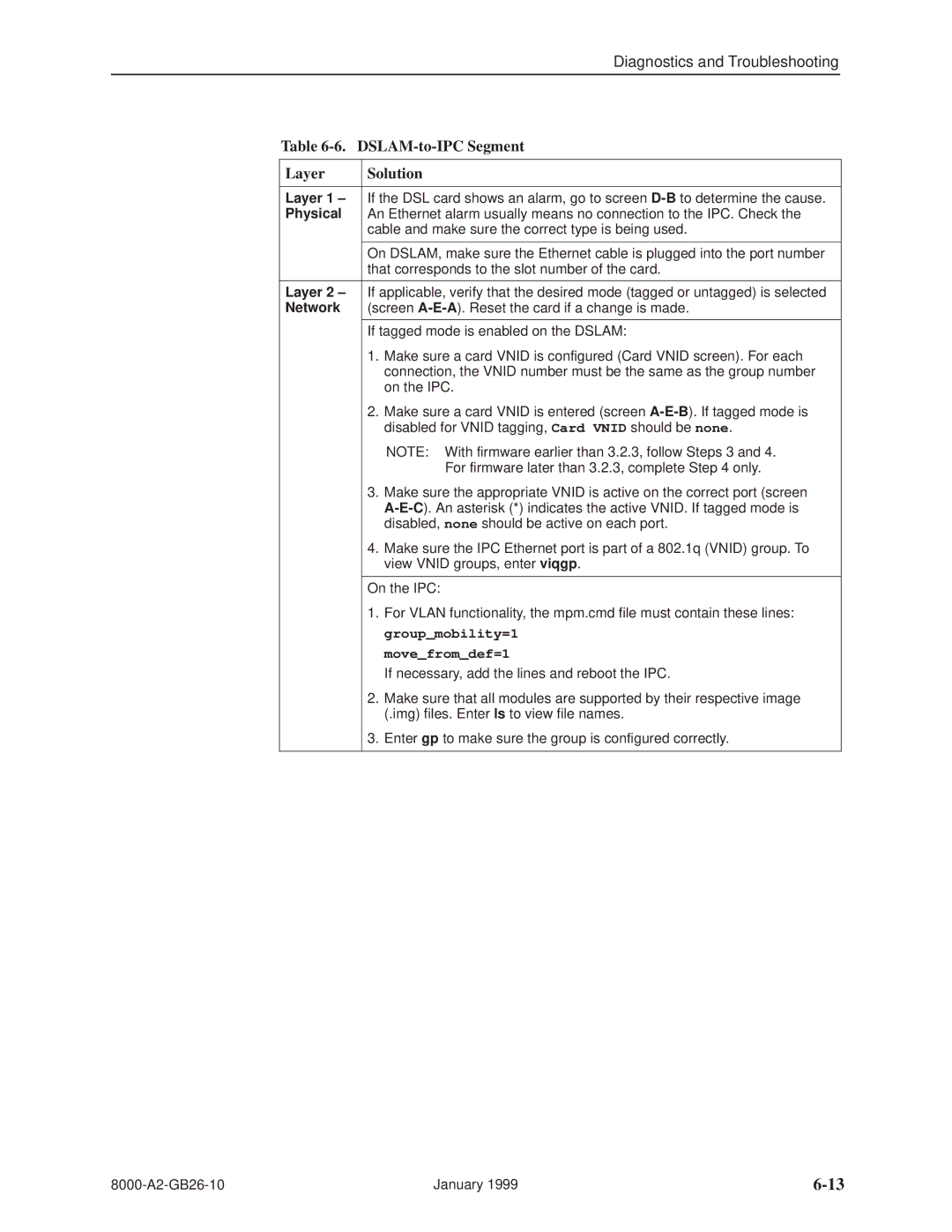
Table 6-6. DSLAM-to-IPC Segment
Layer
Solution
Layer 1 ± | If the DSL card shows an alarm, go to screen | |
Physical | An Ethernet alarm usually means no connection to the IPC. Check the | |
| cable and make sure the correct type is being used. | |
|
| |
| On DSLAM, make sure the Ethernet cable is plugged into the port number | |
| that corresponds to the slot number of the card. | |
|
| |
Layer 2 ± | If applicable, verify that the desired mode (tagged or untagged) is selected | |
Network | (screen | |
|
| |
| If tagged mode is enabled on the DSLAM: | |
| 1. | Make sure a card VNID is configured (Card VNID screen). For each |
|
| connection, the VNID number must be the same as the group number |
|
| on the IPC. |
| 2. | Make sure a card VNID is entered (screen |
|
| disabled for VNID tagging, Card VNID should be none. |
|
| NOTE: With firmware earlier than 3.2.3, follow Steps 3 and 4. |
|
| For firmware later than 3.2.3, complete Step 4 only. |
| 3. | Make sure the appropriate VNID is active on the correct port (screen |
|
| |
|
| disabled, none should be active on each port. |
| 4. | Make sure the IPC Ethernet port is part of a 802.1q (VNID) group. To |
|
| view VNID groups, enter viqgp. |
|
| |
| On the IPC: | |
| 1. | For VLAN functionality, the mpm.cmd file must contain these lines: |
|
| group_mobility=1 |
|
| move_from_def=1 |
|
| If necessary, add the lines and reboot the IPC. |
| 2. | Make sure that all modules are supported by their respective image |
|
| (.img) files. Enter ls to view file names. |
| 3. | Enter gp to make sure the group is configured correctly. |
|
|
|
January 1999 |