•Video Motion: Selects cameras which, when they detect motion, cause the rest of the zone’s cameras to begin recording (refer to Figure 26). Refer to Motion on page 18 for information about zone recording based on motion.
Figure 26. Video Motion Tab for Triggering Cameras in Zone
•Video Loss: Selects cameras whose loss of video cause the rest of the zone’s cameras to begin recording.
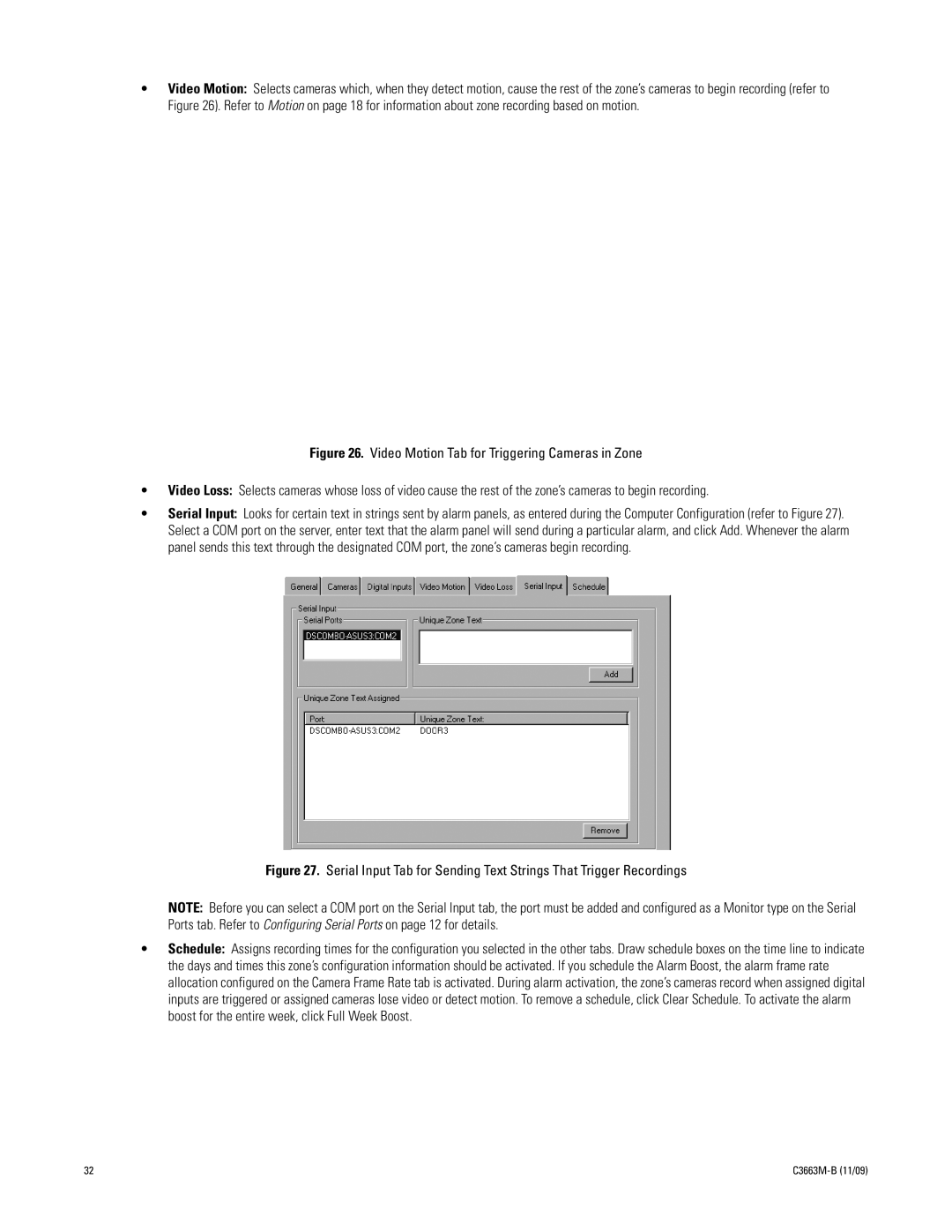
•Serial Input: Looks for certain text in strings sent by alarm panels, as entered during the Computer Configuration (refer to Figure 27). Select a COM port on the server, enter text that the alarm panel will send during a particular alarm, and click Add. Whenever the alarm panel sends this text through the designated COM port, the zone’s cameras begin recording.
Figure 27. Serial Input Tab for Sending Text Strings That Trigger Recordings
NOTE: Before you can select a COM port on the Serial Input tab, the port must be added and configured as a Monitor type on the Serial Ports tab. Refer to Configuring Serial Ports on page 12 for details.
•Schedule: Assigns recording times for the configuration you selected in the other tabs. Draw schedule boxes on the time line to indicate the days and times this zone’s configuration information should be activated. If you schedule the Alarm Boost, the alarm frame rate allocation configured on the Camera Frame Rate tab is activated. During alarm activation, the zone’s cameras record when assigned digital inputs are triggered or assigned cameras lose video or detect motion. To remove a schedule, click Clear Schedule. To activate the alarm boost for the entire week, click Full Week Boost.
32 |
|
