Installation Procedures | Installation |
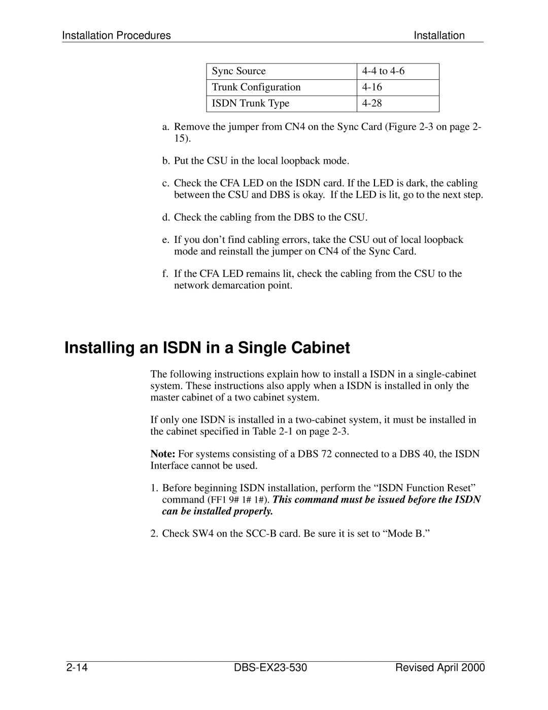
Sync Source | |
|
|
Trunk Configuration | |
|
|
ISDN Trunk Type | |
|
|
a.Remove the jumper from CN4 on the Sync Card (Figure
b.Put the CSU in the local loopback mode.
c.Check the CFA LED on the ISDN card. If the LED is dark, the cabling between the CSU and DBS is okay. If the LED is lit, go to the next step.
d.Check the cabling from the DBS to the CSU.
e.If you don’t find cabling errors, take the CSU out of local loopback mode and reinstall the jumper on CN4 of the Sync Card.
f.If the CFA LED remains lit, check the cabling from the CSU to the network demarcation point.
Installing an ISDN in a Single Cabinet
The following instructions explain how to install a ISDN in a
If only one ISDN is installed in a
Note: For systems consisting of a DBS 72 connected to a DBS 40, the ISDN Interface cannot be used.
1.Before beginning ISDN installation, perform the “ISDN Function Reset” command (FF1 9# 1# 1#). This command must be issued before the ISDN can be installed properly.
2.Check SW4 on the
| Revised April 2000 |
