Installation Procedures | Installation |
6. Set SW1 on the ISDN card according to the following table.
These switch settings correspond to the distance between the DBS and the CSU. To turn a switch on, flip it to the “up” position.
Table
SW |
| Distance from the DBS to the CSU | ||
| 0 to 150 ft. |
|
|
|
SW1 | On |
| Off | Off |
|
|
|
|
|
SW2 | Off |
| On | Off |
|
|
|
|
|
SW3 | Off |
| Off | On |
|
|
|
|
|
SW4 | Off |
| On | Off |
|
|
|
|
|
SW5 | Off |
| Off | On |
|
|
|
|
|
SW6 | Off |
| On | Off |
|
|
|
|
|
SW7 | Off |
| Off | On |
|
|
|
|
|
SW8 | Not used |
| Not used | Not used |
|
|
|
|
|
7.Install the ISDN card in the “EC/TRK” slot
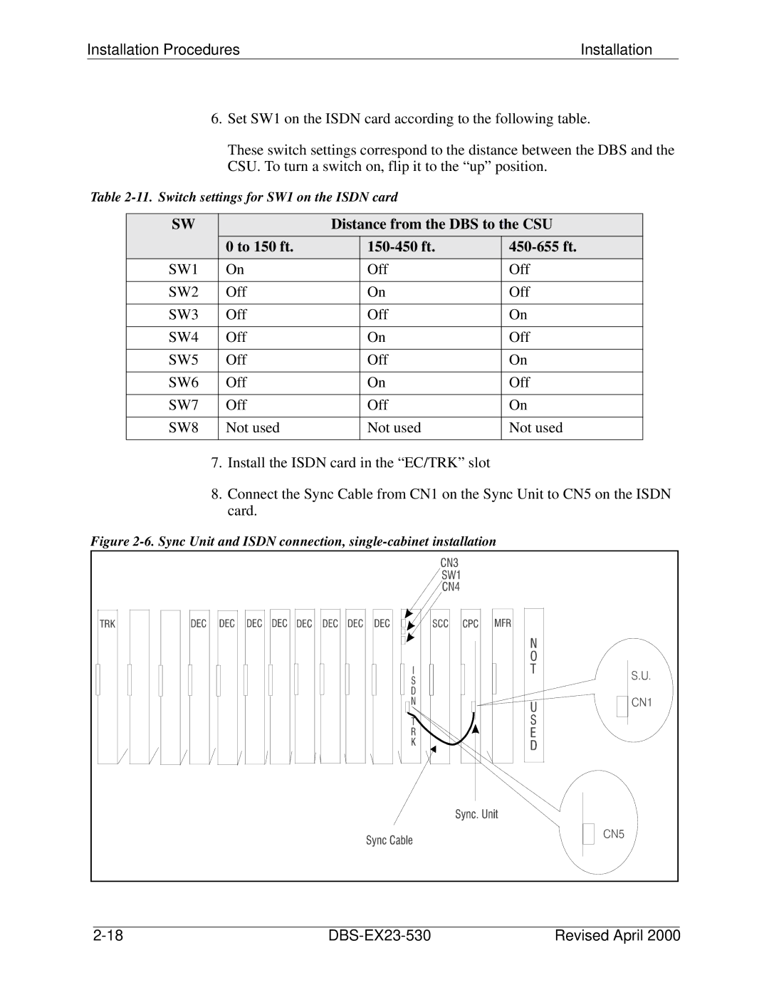
8.Connect the Sync Cable from CN1 on the Sync Unit to CN5 on the ISDN card.
Figure 2-6. Sync Unit and ISDN connection, single-cabinet installation
| Revised April 2000 |
