Alarm Settings |
|
|
| Programming Reference |
| ||||
|
|
|
|
|
|
|
| ||
| Loss of |
| The DBS activates a loss of signal alarm when the | FF key (after the counter is exceeded) |
| ||||
| Signal |
| incoming ISDN signal is not received for more |
| CFA LED on the ISDN card |
| |||
|
|
| than 150 ms. |
|
|
|
| ||
|
|
|
|
|
| OOF LED on the ISDN card |
| ||
|
|
|
|
|
|
|
| ||
|
|
|
|
|
|
| |||
| Note: The LEDs on the ISDN card are normally steadily lit during an alarm condition. However, SLIP |
| |||||||
| alarms cause the SLIP LED to blink rather than light. |
|
|
|
| ||||
|
|
|
|
|
|
|
|
| |
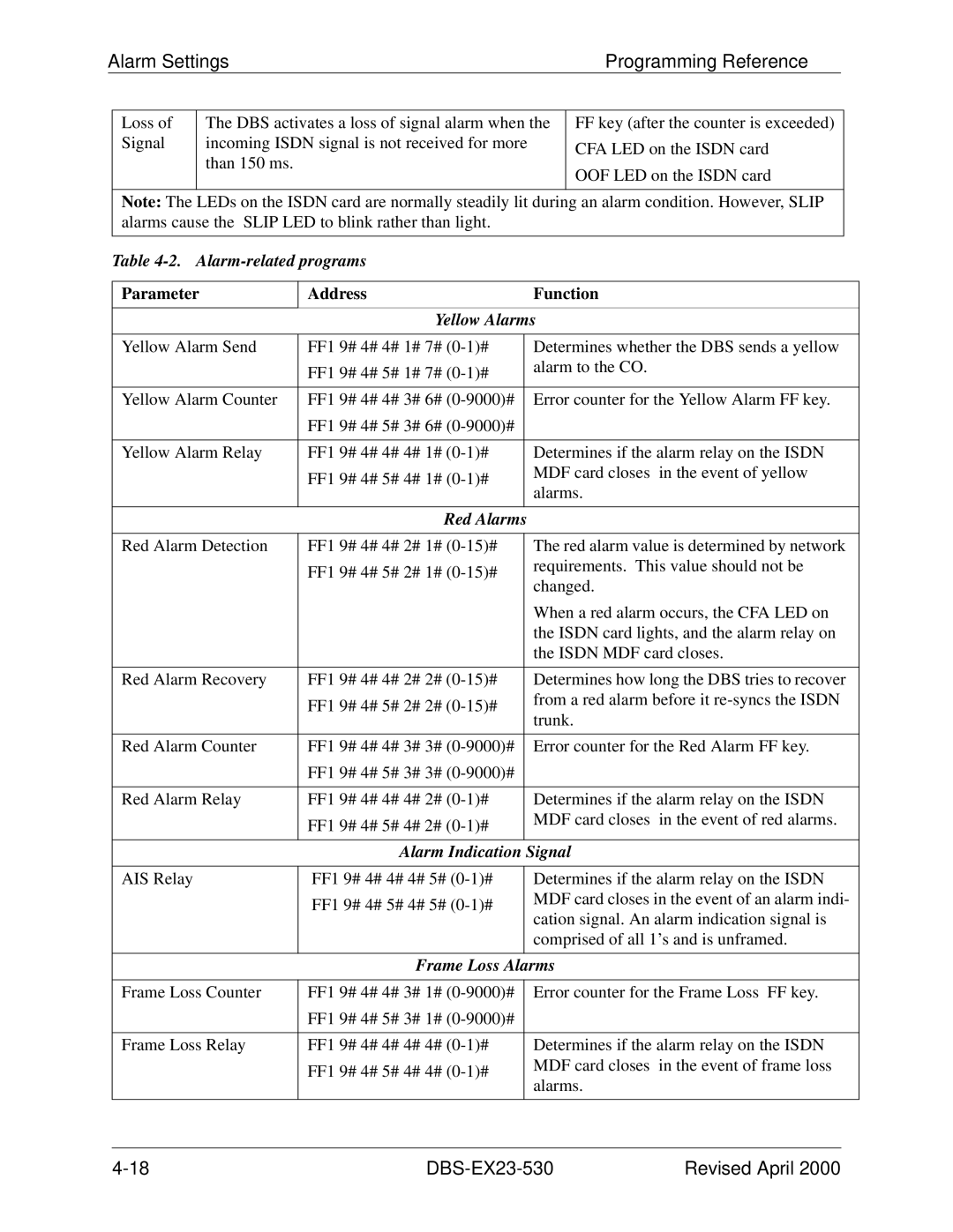
| Table |
|
|
|
| ||||
|
|
|
|
|
| ||||
| Parameter |
| Address | Function | |||||
|
|
|
|
| |||||
|
|
|
| Yellow Alarms | |||||
|
|
|
|
| |||||
| Yellow Alarm Send | FF1 9# 4# 4# 1# 7# |
| Determines whether the DBS sends a yellow | |||||
|
|
|
| FF1 9# 4# 5# 1# 7# |
| alarm to the CO. | |||
|
|
|
|
|
|
|
|
| |
|
|
|
|
| |||||
| Yellow Alarm Counter | FF1 9# 4# 4# 3# 6# |
| Error counter for the Yellow Alarm FF key. | |||||
|
|
|
| FF1 9# 4# 5# 3# 6# |
|
|
|
|
|
|
|
|
|
| |||||
| Yellow Alarm Relay | FF1 9# 4# 4# 4# 1# |
| Determines if the alarm relay on the ISDN | |||||
|
|
|
| FF1 9# 4# 5# 4# 1# |
| MDF card closes in the event of yellow | |||
|
|
|
|
| alarms. | ||||
|
|
|
|
|
| ||||
|
|
|
|
|
|
|
|
|
|
|
|
|
| Red Alarms |
|
|
|
|
|
|
|
|
|
| |||||
| Red Alarm Detection | FF1 9# 4# 4# 2# 1# |
| The red alarm value is determined by network | |||||
|
|
|
| FF1 9# 4# 5# 2# 1# |
| requirements. This value should not be | |||
|
|
|
|
| changed. | ||||
|
|
|
|
|
| ||||
|
|
|
|
|
| When a red alarm occurs, the CFA LED on | |||
|
|
|
|
|
| the ISDN card lights, and the alarm relay on | |||
|
|
|
|
|
| the ISDN MDF card closes. | |||
|
|
|
|
| |||||
| Red Alarm Recovery | FF1 9# 4# 4# 2# 2# |
| Determines how long the DBS tries to recover | |||||
|
|
|
| FF1 9# 4# 5# 2# 2# |
| from a red alarm before it | |||
|
|
|
|
| trunk. | ||||
|
|
|
|
|
| ||||
|
|
|
|
| |||||
| Red Alarm Counter | FF1 9# 4# 4# 3# 3# |
| Error counter for the Red Alarm FF key. | |||||
|
|
|
| FF1 9# 4# 5# 3# 3# |
|
|
|
|
|
|
|
|
|
| |||||
| Red Alarm Relay | FF1 9# 4# 4# 4# 2# |
| Determines if the alarm relay on the ISDN | |||||
|
|
|
| FF1 9# 4# 5# 4# 2# |
| MDF card closes in the event of red alarms. | |||
|
|
|
|
|
|
|
|
| |
|
|
|
|
|
| ||||
|
|
|
| Alarm Indication | Signal | ||||
|
|
|
|
|
| ||||
| AIS Relay |
| FF1 9# 4# 4# 4# 5# |
| Determines if the alarm relay on the ISDN | ||||
|
|
|
| FF1 9# 4# 5# 4# 5# |
| MDF card closes in the event of an alarm indi- | |||
|
|
|
|
| cation signal. An alarm indication signal is | ||||
|
|
|
|
|
| ||||
|
|
|
|
|
| comprised of all 1’s and is unframed. | |||
|
|
|
|
|
| ||||
|
|
|
| Frame Loss Alarms | |||||
|
|
|
|
| |||||
| Frame Loss Counter | FF1 9# 4# 4# 3# 1# |
| Error counter for the Frame Loss FF key. | |||||
|
|
|
| FF1 9# 4# 5# 3# 1# |
|
|
|
|
|
|
|
|
|
| |||||
| Frame Loss Relay | FF1 9# 4# 4# 4# 4# |
| Determines if the alarm relay on the ISDN | |||||
|
|
|
| FF1 9# 4# 5# 4# 4# |
| MDF card closes in the event of frame loss | |||
|
|
|
|
| alarms. | ||||
|
|
|
|
|
| ||||
|
|
|
|
|
|
|
|
|
|
| Revised April 2000 |