ActivMedia Robotics

disengage the motors while charging, such as by disconnecting, you will have to re- engage them from the client or by manually pressing the MOTORS button on the controller. Re-engaging the motors automatically retracts the charging mechanism.

While the motors are engaged, the charging mechanism cannot be deployed, except by the CHARGE command. For best control and safety, consider also using the AROS CHARGE command number 68 with integer argument 0 to gracefully cancel charging, retract the charging mechanism, and restore motor state.

In addition to the client-mediated commands, you also may cancel recharging and retract the charging mechanism manually with the Charge Deploy button, as described in the earlier sections. Do note that client-mediated docking/charging behaviors may act to reverse your actions.

For example, the client may, upon untimely loss of recharging power resulting from someone pressing the Charge Deploy button, may re-engage the motors and have the robot automatically attempt to re-dock with the charging platform and restart charging.

Your client software may disengage and re-engage the client-server connection without disrupting recharging, as long as the robot remains positively engaged with the charging platform and you don't do anything else to otherwise disrupt recharging. Once disengaged from the client, the rules for engaging and disengaging the recharge mechanism and power manually apply.

Monitoring the Recharge Cycle

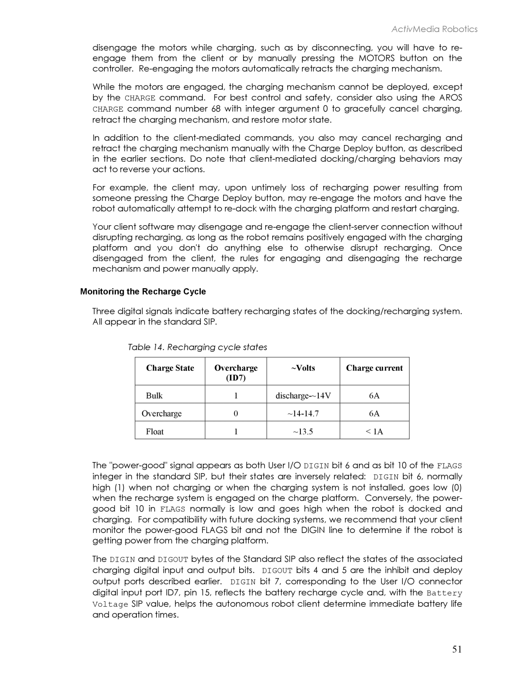
Three digital signals indicate battery recharging states of the docking/recharging system. All appear in the standard SIP.

Table 14. Recharging cycle states

Charge State

Overcharge

~Volts

Charge current


(ID7)


Bulk

1

discharge-~14V

6A


Overcharge

0

~14-14.7

6A


Float

1

~13.5

< 1A


The "power-good" signal appears as both User I/O DIGIN bit 6 and as bit 10 of the FLAGS integer in the standard SIP, but their states are inversely related: DIGIN bit 6, normally high (1) when not charging or when the charging system is not installed, goes low (0) when the recharge system is engaged on the charge platform. Conversely, the power- good bit 10 in FLAGS normally is low and goes high when the robot is docked and charging. For compatibility with future docking systems, we recommend that your client monitor the power-good FLAGS bit and not the DIGIN line to determine if the robot is getting power from the charging platform.

The DIGIN and DIGOUT bytes of the Standard SIP also reflect the states of the associated charging digital input and output bits. DIGOUT bits 4 and 5 are the inhibit and deploy output ports described earlier. DIGIN bit 7, corresponding to the User I/O connector digital input port ID7, pin 15, reflects the battery recharge cycle and, with the Battery Voltage SIP value, helps the autonomous robot client determine immediate battery life and operation times.

51
Page 57
Image 57
Pioneer 2TM, 3TM manual Monitoring the Recharge Cycle, Charge State Overcharge ~Volts Charge current ID7