Appendix A: Ports and Connections
Serial Ports
Two
The AUX1 and AUX2 serial ports are for
AROS operates the serial ports at any of the common data rates: 9,600, 19,200, 38,400, 57,800, or 115,200 bits per second; and at eight data bits, one stop bit, no parity or hardware handshaking.
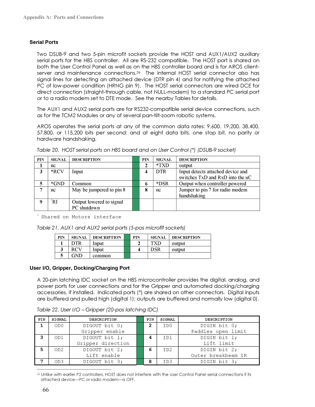
Table 20. HOST serial ports on H8S board and on User Control (*)
PIN | SIGNAL | DESCRIPTION |
| PIN | SIGNAL | DESCRIPTION |
1 | nc |
|
| 2 | *TXD | output |
3 | *RCV | Input |
| 4 | DTR | Input detects attached device and |
|
|
|
|
|
| switches TxD and RxD into the uC |
5 | *GND | Common |
| 6 | *DSR | Output when controller powered |
7 | nc | May be jumpered to pin 8 |
| 8 | nc | Jumper to pin 7 for radio modem |
|
|
|
|
|
| handshaking |
9 | †RI | Output lowered to signal |
|
|
|
|
|
| PC shutdown |
|
|
|
|
†Shared on Motors interface
Table 21. AUX1 and AUX2 serial ports
PIN | SIGNAL | DESCRIPTION |
| PIN | SIGNAL | DESCRIPTION |
1 | DTR | Input |
| 2 | TXD | output |
3 | RCV | Input |
| 4 | DSR | output |
5 | GND | common |
|
|
|
|
User I/O, Gripper, Docking/Charging Port
A
Table 22. User I/O – Gripper
| PIN | SIGNAL | DESCRIPTION |
| PIN | SIGNAL | DESCRIPTION | |
1 | OD0 | DIGOUT bit 0; |
| 2 | ID0 | DIGIN bit 0; | ||
|
|
| Gripper enable |
|
|
| Paddles open limit | |
3 | OD1 | DIGOUT bit 1; |
| 4 | ID1 | DIGIN bit 1; | ||
|
|
| Gripper direction |
|
|
| Lift limit | |
5 | OD2 | DIGOUT bit 2; |
| 6 | ID2 | DIGIN bit 2; | ||
|
|
| Lift enable |
|
|
| Outer breakbeam IR | |
7 | OD3 | DIGOUT bit 3; |
| 8 | ID3 | DIGIN bit 3; | ||
|
|
|
|
|
|
|
|
|
26Unlike with earlier P2 controllers, HOST does not interfere with the User Control Panel serial connections if its attached
66