Pioneer H8-Series Operations Manual
Page
Important Safety Instructions
Table of Contents
Operating the Aria Demonstration Client
Appendix C
Robot Package
Introduction
Basic Components all shipments
Optional Components and Attachments partial list
Additional Resources
User-Supplied Components / System Requirements
Support Website
Newsgroups
Support@activmedia.com
Support
Pioneer Reference Platform
What Is Pioneer?
Hitachi H8S-BASED Microcontroller
Plus MOTOR-POWER Board
Http//robots.activmedia.com
Client Software
Pioneer Legacy
Supporting Software
Pioneer 2 and PeopleBot
Pioneer 1 and AT
ActivMedia Robotics
Maintenance and Standalone Modes
Server Mode
Modes of Operation
Joydrive and Self Test Modes
Physical Characteristics
Specifications & Controls
Motor Stop Button
Main Components
P3-DX User Control Panel
User Control Panel
Sonar Arrays with Gain Adjustment
Body, Nose, and Accessory Panels
Motors, Wheels, and Position Encoders
Batteries and Power
Recharging
Battery Indicators and Low Voltage Conditions
Manual Operation Robot Power and Systems on
Manual Operation Robot Power OFF
DOCKING/CHARGING System
Client-server connection options
Radio Controls and Accessories
Computer Control Panel
Onboard PC
PC Networking
Operating the Onboard PC
UPS and Genpowerd
Safety Aros Watchdogs
Install Aria
Preparative Assembly
Quick Start
Client-Server Communications
Install Batteries
Starting UP Client and Server
Drive Self-Test
Ipthru
Demo Startup Options
Operating the Aria Demonstration Client
Successful Connection
Quickstart Troubleshooting
Disconnecting
Proper Connections
SRIsim
OFF
Joydrive and Self-Tests
Joydrive Mode
Engaging SELF-TESTS
CLIENT-SERVER Communication Packet Protocols
ActivMedia Robotics Operating System
Packet Checksum
Packet Errors
Multiply by DistConvFactor‡
Server Information Packets
Before Client Connection
Client Commands
P2OS
CLIENT-SERVER Connection
Opening the Servers-OPEN
Autoconfiguration SYNC2
Keeping the Beat-PULSE
Closing the Connection-CLOSE
Rotation
Motion Commands
Platform Dependent and Independent Variables
ActivMedia Robots in Motion
Internal coordinate system
PID Controls
Position Integration
Enable/Disabling Sonar
Sonar
Polling Sequence and Rate
11-15 Reserved
Stalls and Emergencies
Packet Processing
Accessory Commands and Packets
Serial Port Communications
CONFIGpac and Config Command
Changing Baud Rates and Autobauding
Encoder Packets
HOST-to-AUX Serial Transfers
Gripper packets
TCM2
Sounds
Heading Correction Gyro
Onboard PC
User I/O
Input Output I/O
IO packets
Bumper and IR I/O
DOCKING/CHARGING System I/O
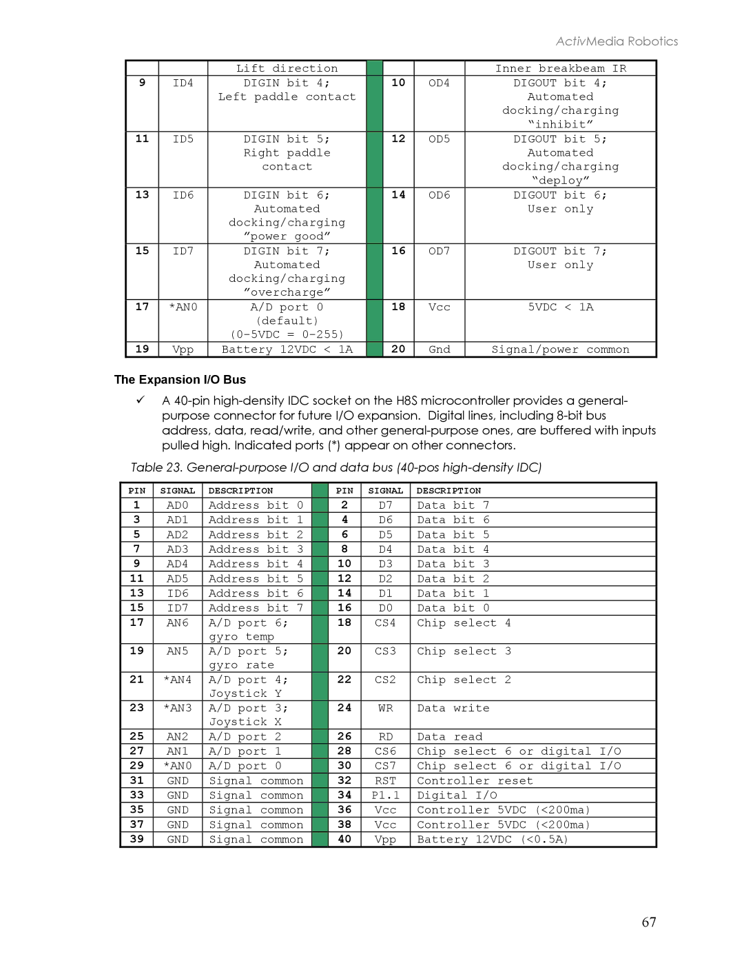
Expansion I/O
Digital Port Controls
Docking/Charging Servers
Charge State Overcharge ~Volts Charge current ID7
Monitoring the Recharge Cycle
ActivMedia Robotics Operating System
Where to GET Aros Software
Updating & Reconfiguring Aros
Aros Maintenance Mode
Simple Aros Updates
Starting Aroscf
Updating and Reconfiguring Aros
Interactive Commands
Configuring Aros Operating Parameters
Changing Parameters
PID Parameters
Save Your Work
Keyword
0056 0057 0060 0034
Ticksmm and Revcount
Bumpers
Stallval and Stallcount
Updating and Reconfiguring Aros
Tire Inflation
Maintenance & Repair
Drive Lubrication
Batteries
Automated Docking/Charging System
Alternative Battery Chargers
Tightening the AT Drive Belt
Removing the Nose
Getting Inside
Factory Repairs
Opening the Deck
Appendix a
Power Connector
H8S Ports & Connections
H8S Microcontroller
User I/O, Gripper, Docking/Charging Port
Serial Ports
Expansion I/O Bus
OD7
Motors, Encoders, and IR Sensors
Bumper Ports
User Control Interface
Joystick Port
Configuration for Current and Temperature Sensing
Pioneer 3 and 2-PLUS MOTOR-POWER Board
Appendix B
Radio, Auxiliary, and User Power Connectors
Controller Power and Interface
GND
IR Signal and Power
Appendix C
Radio Modem Settings
Console mode
Serial Ethernet Settings
Appendix D
Peer-to-Peer Networking
Webpage
Appendix E
Specifications
Controls and Ports
Warranty & Liabilities
Columbia Drive Amherst, NH 603