ActivMedia Robotics Operating System
modifications to the robot's heading are done on the client side, as supported in the latest versions (1.3 and later) of ARIA.
To enable the gyro, you must set the HasGyro FLASH parameter to 1 using the AROScf tool (see next chapter). Set it to 0 if the gyro isn't attached. Then to acquire gyro data, send the GYRO client command #58 with integer argument of one; zero disables the gyro SIP. The gyro SIP is stopped upon client disconnection or controller reset, too.
AROS collects the gyro rate and temperature readings at the maximum rate of once every 25 milliseconds and reports each of these values to the client, when enabled, in the GYROpac SIP that gets sent just before the standard Server Information Packet every sInfoCycle, typically every 100ms. GYROpac consists of a count byte of the rate and temperature data pairs accumulated since the last cycle (typically 4 for a 100ms cycle time), followed by that number of rate/temperature integer/byte pairs.
Gyro rates are
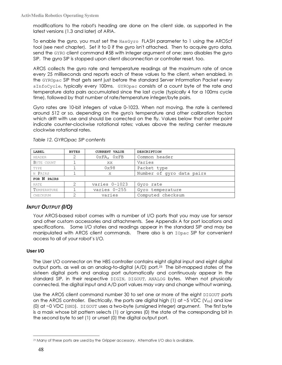
Table 12. GYROpac SIP contents
LABEL | BYTES | CURRENT VALUE | DESCRIPTION |
HEADER | 2 | 0xFA, 0xFB | Common header |
BYTE COUNT | 1 | xx | Varies |
TYPE | 1 | 0x98 | Packet type |
N PAIRS | 1 | x | Number of gyro data pairs |
FOR N PAIRS |
|
|
|
RATE | 2 | varies | Gyro rate |
TEMPERATURE | 1 | varies | Gyro temperature |
CHECKSUM | 2 | varies | Computed checksum |
INPUT OUTPUT (I/O)
Your
User I/O
The User I/O connector on the H8S controller contains eight digital input and eight digital output ports, as well as an
Use the AROS client command number 30 to set one or more of the eight DIGOUT ports on the AROS controller. Electrically, the ports are digital high (1) at ~5 VDC (Vcc) and low
(0)at ~0 VDC (GND). DIGOUT uses a
23Many of these ports are used by the Gripper accessory. Alternative I/O also is available.
48