Powerware 9395 UPS 1000-1100 kVA
Consignes DE Sécurité Importantes Conserver CES Instructions
Table of Contents
Single UPS Modes Normal Mode Bypass Mode Battery Mode
Status Indicators System Events
Using the Menu Mimic Screen
Initial Startup
ENotify Service
Terminal Mode
UPS Maintenance
Starting the UPMs
Product Specifications 10−1 10.1
10.2
10.2.1 UPS Input 10−1 10.2.2 UPS Output 10−2 10.2.3
List of Figures
Powerware Hot Sync can Bridge Card
Chapter Introduction
UPS Standard Features
Installation Features
Control Panel
Advanced Battery Management
Customer Interface
Options and Accessories
Power Management Software
Field Installed UPM
Inherent Redundancy
Battery System
Distributed Bypass System
Monitoring and Communication
Basic System Configurations
Using This Manual
Conventions Used in This Manual
Symbols, Controls, and Indicators
For More Information
Getting Help
Chapter Safety Warnings
E R T I S S E M E N T
Section
Page
Creating an Installation Plan
Environmental and Installation Considerations
Preparing the Site
UPS Cabinet Weights
UPS Cabinet Clearances
95%, noncondensing
Dimensions are in millimeters inches
Isbm Section Dimensions Front View
Front
Isbm Section Center of Gravity
114.3 115.8 Front View
UPS System Power Wiring Preparation
Common Battery
AC Input to UPS Bypass Five Wire Full Load Current
Phases, 1 Neutral, 1 Ground Minimum Conductor Size
DC Input from Each Battery Disconnect to Each UPS UPM
AC Output to Critical Load Five Wire Full Load Current
650 750 825 591 682
−12
Supplied Intercabinet Wiring Terminal Hardware Kit
Battery
Battery UPM
Battery UPM 4 FI−UPM
Terminal Function Bus Landings Tightening Torque Bolt Size
11. Supplied External Wiring Terminal Hardware Kit
Part Size Quantity Manufacturer Part Number
Long Barrel 2-Hole Lug
Manual Hydraulic Crimp Tool
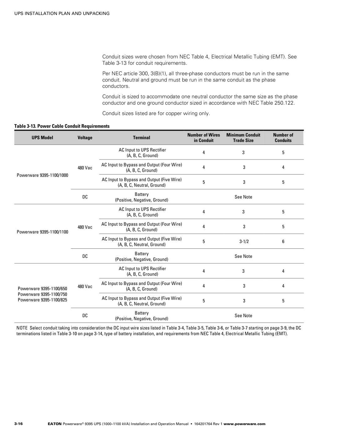
13. Power Cable Conduit Requirements
UPS Model Voltage Terminal Number of Wires Minimum Conduit
14. Recommended Input Circuit Breaker Ratings
UPS Model Input Rating
UPS Model Output Rating
UPS Model
UPS System Interface Wiring Preparation
Distributed Bypass Power Wiring Preparation
Inspecting and Unpacking the UPS Cabinets
11. UPS Cabinet as Shipped on Pallet Isbm Section
12. UPS Cabinet as Shipped on Pallet UPM Section
This page intentionally left blank
Preliminary Installation Information
Unloading the UPS Sections from the Pallet
Front Door Shipping Bracket Bolts Pallet Left Side Shipping
Removing the Isbm Section Right Side Shipping Bracket
Bolts
Mechanically Joining the Sections
Right Side Shipping Bracket Bolts
U T I O N
UPM Wireway
Electrically Connecting the Sections
Screw from Kit Bracket from Kit
Section Top Screw from Kit
Back
UPS System Installation
−10
Phase B
Phase B E2A
UPM 4 FI−UPM Four UPM Model
Orange
UPM 1 Cable 1G1 & 1G2 Brown
Cable 1G3 Red UPM 1 1E4A
DC Input to UPMs UPM 2 2E4A
Cable 2G3 Black Cable 3G3 Black UPM 3 3E5A
UPM 1 Cable 1G4 & 1G5 Orange UPM 2 Cable 2G4 & 2G5 Orange
Wiring Access
Protective Cage
Location of J50
J51, J61, and J70
Pl1 Interface Board J39 Inverter can Connector
Field Installed UPM Installation
Battery System Installation
Distributed Bypass Tie Cabinet Installation
Installing UPS External and Battery Power Wiring
Isbm Section
UPM Section Front
16. Isbm Section Conduit and Wire Entry Locations
U T I O N
1A = 2A = 3A = 4A 1B = 2B = 3B = 4B
21 for Detail BB DC Input from Battery E5
21 for Detail BB Neutral E12
Ground Terminals Front Phase C E3 Phase B E2 AC Input to
Phase a E1 Phase a E6 Phase B E7 AC Input to
Phase C E8 Section A-A
Battery Power Wiring
DC Input from Battery + E4 DC Input from Battery E5
Section B-B
21. Isbm Section Power Terminal Detail CC Separate Battery
Installing Interface Connections
22. Isbm Section Interface Terminal Locations
4−33 for detail
TB1, TB2, and TB3 Interface Connections
For terminal
Assignments
Battery Aux
Battery Aux Common
Battery Shunt Trip +
Battery Shunt Trip
2 TB1 Battery Interface Connections
Battery Aux Battery Aux Common
Battery Disconnect 48 Vdc
Battery Aux Battery Aux Return
Battery Disconnect
3 X−Slot Connections
−Slot Communication Bay
Installing a Repo Switch
Repo Switch Front View
Repo Wire Terminations
Return
Wires
Twisted
Completing the Installation Checklist
Initial Startup
Installation Checklist
Distributed Bypass Installation Checklist
−40
Installing an Optional Powerware Hot Sync can Bridge Card
Plug−in Terminal Block J3
Installing Options and Accessories
J3 Terminal Name Description Alarm
Normally-closed contact opens when UPS is on bypass
Normally-open contact closes when UPS is on bypass
Bypass contact return
Installing Distributed Bypass Control Wiring
If Installed
Shielded Twisted Pair
From
Twisted Pair
AUX
Pull−Chain Wiring Terminations with MOBs
UPS 2 can Bridge Card J3-1 Alarm MOB 2 Aux 1 NC
UPS 3 can Bridge Card J3-1 Alarm MOB 3 Aux 1 NC
UPS 4 can Bridge Card J3-1 Alarm MOB 4 Aux 1 NC
Installing an Optional Remote Monitor Panel
Ground Terminal Terminal TB3 Vac Power
From Tightening Torque Remarks
RMP II, RIM II, or SCM Nm lb
Installing an Optional Relay Interface Module
J1 through J4 Interface Connectors
Installing an Optional Supervisory Contact Module
Terminal TB3 Vac Power Ground Terminal TB2 Customer
Terminal TB1 Signal
11. Supervisory Contact Module II TB2
Accessory Mounting Dimensions
13. Relay Interface Module II Dimensions
14. Supervisory Contact Module II Dimensions
This page intentionally left blank
Operation
−20
Battery System
UPS System Overview
UPS Cabinet
Normal Mode
Single UPS
Modes
Bypass Mode
Battery Converter
Rectifier
Inverter
Battery Mode
Path of Current Through the UPS in Battery Mode
Single UPS Unit System Oneline Configurations
Fuse Battery Contactor K2
Battery Breaker
Service Connector
E1, E2, E3 E6, E7
E1, E2, E3 E6, E7 Interface Board E8, E12
Contactor Rectifier
Output Contactor
Converter Fuse Battery Contactor K2
E4. E5 Battery Breaker
Rectifier Fuse Inverter Output
Rectifier Fuse
Fuse Inverter Output
Converter Fuse
AC Input
Rectifier Input Breaker
Bypass Input Breaker
Multiple UPS Distributed Bypass System
Multiple UPS Parallel System Modes
Normal Mode Distributed Bypass
Bypass Mode Distributed Bypass
Battery Mode Distributed Bypass
Main Power Flow Open
+1 and 2+0 Configurations
+1 and 3+0 Configurations
+1 and 4+0 Configurations
Multiple UPS Distributed Bypass
TIE
Fuse Inverter Battery Converter
E4. E5 Battery Breaker
UPS Controls and Indicators
Control Panel AC Input Breaker CB1 Optional
Using the Control Panel
Circuit Breaker
Status Indicators
Status Indicators
System Events
Events Meters Controls Setup
Using the LCD and Pushbuttons
Using the Menu
Mimic Screen
Display Menu Operation
Display Menu Operation
Function Subfunction Operation Contrast Adjust
System Setup screen, press the return arrow pushbutton
System Level 1 Setup Password
Password is L1
System Status Screen and Controls
Function Subfunction Operation Com Port Selection
Control See paragraph 7.2.7 for details
Command Menu Operation
Typical System Status Messages
Cancel Load OFF
Load Off Screen
Starting the UPS in Normal Mode
Single UPS Operation
Starting the UPS in Bypass Mode
Starting the UPMs
−13
Transfer from Normal to Bypass Mode
Transfer from Bypass to Normal Mode
Power is present inside the UPS cabinet sections
Transfer from Normal to Bypass Mode and Shut Down UPS
Single UPM Shutdown
UPS and Critical Load Shutdown
Charger Control
Using the UPS Load OFF Pushbutton or Command
Using the Remote Emergency Power−off Switch
Repo Operation
Starting the Distributed Bypass System in Normal Mode
Multiple UPS Distributed Bypass Operation
Starting the Distributed Bypass System in Bypass Mode
Starting the UPSs UPMs
−22
R N I N G
Transfer from Normal to Bypass Mode and Shut Down all UPSs
UPS and Critical Load Shutdown
U T I O N
Using the Remote Emergency Power−off Switch
−28
Chapter Communication
X−Slot Cards
ENotify Service
ENotify Service Features
Installing eNotify Service
ConnectUPS−X Web/SNMP Card Modbus Card Modem Card
Powerware LanSafe Power Management Software
Remote Notification
Terminal Mode
Display UPS Control Panel
Event History Log
CSB Bootloader Display
CTO TF12710000000
Building Alarm Monitoring
General Purpose Relay Contact
Remote Monitor Panel
RMP II Status Indicators
System Normal
Customer Interface Connectors
Pins 3 Contacts are open when the UPS is offline
Pins 6 Contacts are closed when Utility Failure is detected
Relay Interface Module
SCM II Status Indicators and Connections
Supervisory Contact Module
Chapter UPS Maintenance
Important Safety Instructions
Performing Preventive Maintenance
Daily Maintenance
Monthly Maintenance
Verify washed filters are thoroughly dry before reinstalling
Isbm Air Filters
Verify washed filter is thoroughly dry before reinstalling
UPM Air Filters
Installing Batteries
Periodic Maintenance
Annual Maintenance
Battery Maintenance
Recycling the Used Battery or UPS
Maintenance Training
Specifications
Model Numbers
UPS Input
UPS Output
UPS Environmental
Warranty
Warranty
Page
1642017641