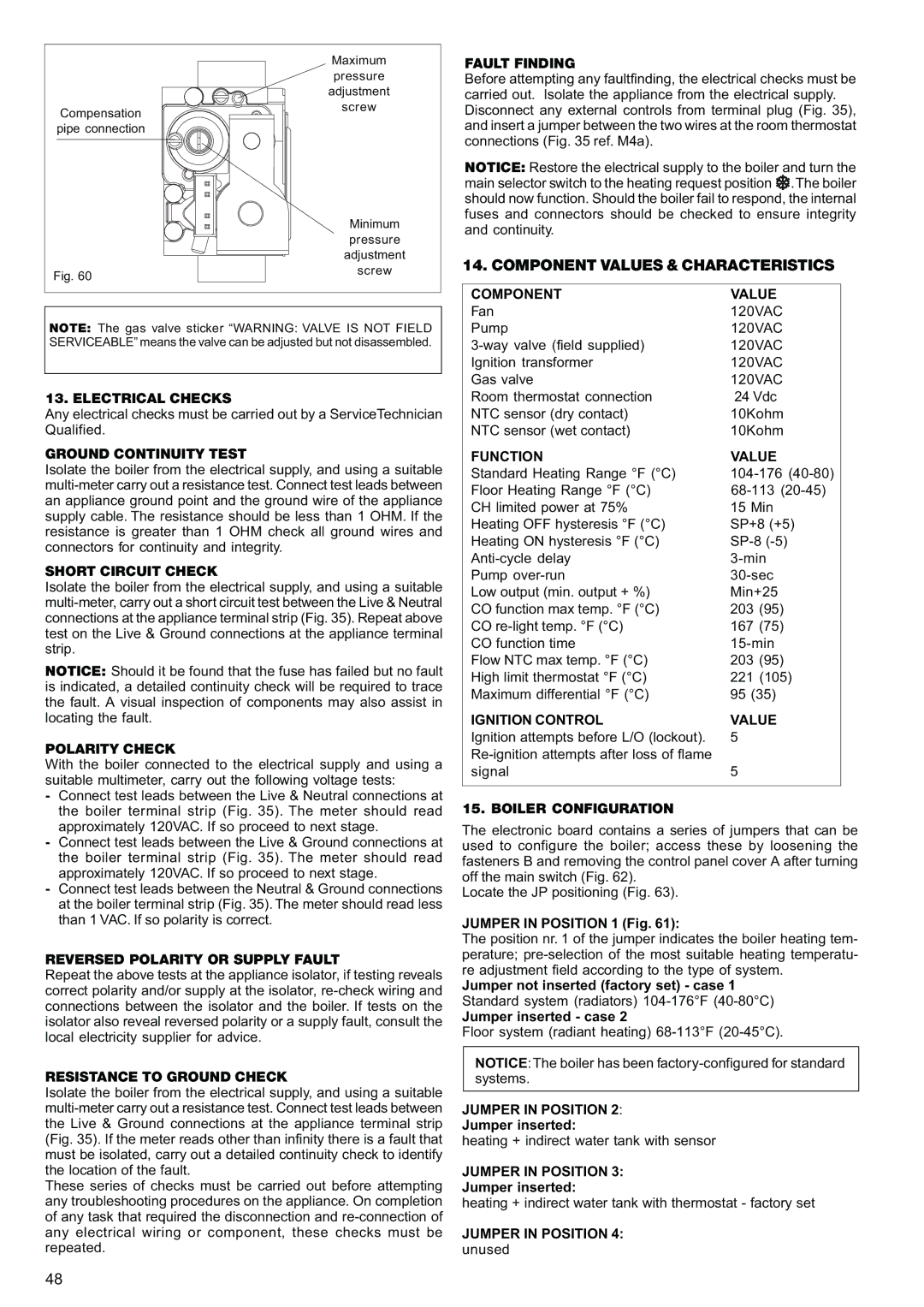
Compensation pipe connection

Fig. 60

Maximum pressure adjustment screw

Minimum pressure adjustment screw

FAULT FINDING

Before attempting any faultfinding, the electrical checks must be carried out. Isolate the appliance from the electrical supply. Disconnect any external controls from terminal plug (Fig. 35), and insert a jumper between the two wires at the room thermostat connections (Fig. 35 ref. M4a).

NOTICE: Restore the electrical supply to the boiler and turn the main selector switch to the heating request position .The boiler should now function. Should the boiler fail to respond, the internal fuses and connectors should be checked to ensure integrity and continuity.

14. COMPONENT VALUES & CHARACTERISTICS

NOTE: The gas valve sticker “WARNING: VALVE IS NOT FIELD SERVICEABLE” means the valve can be adjusted but not disassembled.

13. ELECTRICAL CHECKS

Any electrical checks must be carried out by a ServiceTechnician Qualified.

GROUND CONTINUITY TEST

Isolate the boiler from the electrical supply, and using a suitable multi-meter carry out a resistance test. Connect test leads between an appliance ground point and the ground wire of the appliance supply cable. The resistance should be less than 1 OHM. If the resistance is greater than 1 OHM check all ground wires and connectors for continuity and integrity.

SHORT CIRCUIT CHECK

Isolate the boiler from the electrical supply, and using a suitable multi-meter, carry out a short circuit test between the Live & Neutral connections at the appliance terminal strip (Fig. 35). Repeat above test on the Live & Ground connections at the appliance terminal strip.

NOTICE: Should it be found that the fuse has failed but no fault is indicated, a detailed continuity check will be required to trace the fault. A visual inspection of components may also assist in locating the fault.

POLARITY CHECK

With the boiler connected to the electrical supply and using a suitable multimeter, carry out the following voltage tests:

-Connect test leads between the Live & Neutral connections at the boiler terminal strip (Fig. 35). The meter should read approximately 120VAC. If so proceed to next stage.

-Connect test leads between the Live & Ground connections at the boiler terminal strip (Fig. 35). The meter should read approximately 120VAC. If so proceed to next stage.

-Connect test leads between the Neutral & Ground connections at the boiler terminal strip (Fig. 35). The meter should read less than 1 VAC. If so polarity is correct.

REVERSED POLARITY OR SUPPLY FAULT

Repeat the above tests at the appliance isolator, if testing reveals correct polarity and/or supply at the isolator, re-check wiring and connections between the isolator and the boiler. If tests on the isolator also reveal reversed polarity or a supply fault, consult the local electricity supplier for advice.

RESISTANCE TO GROUND CHECK

Isolate the boiler from the electrical supply, and using a suitable multi-meter carry out a resistance test. Connect test leads between the Live & Ground connections at the appliance terminal strip (Fig. 35). If the meter reads other than infinity there is a fault that must be isolated, carry out a detailed continuity check to identify the location of the fault.

These series of checks must be carried out before attempting any troubleshooting procedures on the appliance. On completion of any task that required the disconnection and re-connection of any electrical wiring or component, these checks must be repeated.

COMPONENT

VALUE

Fan

120VAC

Pump

120VAC

3-way valve (field supplied)

120VAC

Ignition transformer

120VAC

Gas valve

120VAC

Room thermostat connection

24 Vdc

NTC sensor (dry contact)

10Kohm

NTC sensor (wet contact)

10Kohm

FUNCTION

VALUE

Standard Heating Range °F (°C)

104-176 (40-80)

Floor Heating Range °F (°C)

68-113 (20-45)

CH limited power at 75%

15 Min

Heating OFF hysteresis °F (°C)

SP+8 (+5)

Heating ON hysteresis °F (°C)

SP-8 (-5)

Anti-cycle delay

3-min

Pump over-run

30-sec

Low output (min. output + %)

Min+25

CO function max temp. °F (°C)

203 (95)

CO re-light temp. °F (°C)

167 (75)

CO function time

15-min

Flow NTC max temp. °F (°C)

203 (95)

High limit thermostat °F (°C)

221 (105)

Maximum differential °F (°C)

95 (35)

IGNITION CONTROL

VALUE

Ignition attempts before L/O (lockout).

5

Re-ignition attempts after loss of flame


signal

5

15. BOILER CONFIGURATION

The electronic board contains a series of jumpers that can be used to configure the boiler; access these by loosening the fasteners B and removing the control panel cover A after turning off the main switch (Fig. 62).

Locate the JP positioning (Fig. 63).

JUMPER IN POSITION 1 (Fig. 61):

The position nr. 1 of the jumper indicates the boiler heating tem- perature; pre-selection of the most suitable heating temperatu- re adjustment field according to the type of system.

Jumper not inserted (factory set) - case 1 Standard system (radiators) 104-176°F(40-80°C)

Jumper inserted - case 2

Floor system (radiant heating) 68-113°F (20-45°C).

NOTICE: The boiler has been factory-configured for standard systems.

JUMPER IN POSITION 2:

Jumper inserted:

heating + indirect water tank with sensor

JUMPER IN POSITION 3:

Jumper inserted:

heating + indirect water tank with thermostat - factory set

JUMPER IN POSITION 4:

unused

48

Page 48
Image 48
Raypak 85 Fault Finding, Electrical Checks, Ground Continuity Test, Short Circuit Check, Polarity Check, Component Value

120, 85 specifications

The Raypak 120,85 is a prominent model in the realm of pool and spa heating solutions, designed to deliver unmatched efficiency and performance. Renowned for its robust features and innovative technologies, the Raypak 120,85 stands out as a reliable choice for homeowners seeking to maintain the perfect water temperature in their pools and spas.

One of the primary characteristics of the Raypak 120,85 is its impressive heating capacity. With a total output of 120,000 BTUs, this heater quickly and efficiently warms up water, ensuring that users can enjoy comfortable swimming conditions regardless of the outdoor temperature. The 85 indicates its ability to deliver consistent performance even in cooler climates, making it an adaptable option for various geographical locations.

The Raypak 120,85 is equipped with a state-of-the-art, copper fin tube heat exchanger, which provides superior heat transfer efficiency. This technology enhances the heater's ability to warm water rapidly while maintaining energy efficiency. Additionally, the copper material is known for its durability and resistance to corrosion, ensuring a long lifespan for the heat exchanger.

Another key feature of the Raypak 120,85 is its electronic ignition system. This innovation eliminates the need for a standing pilot light, which not only saves energy but also enhances safety by reducing the risk of gas leaks associated with traditional ignition systems. The electronic ignition provides precise control, ensuring a reliable start each time.

The Raypak 120,85 also boasts a digital display control panel, allowing users to easily monitor and adjust the water temperature settings. This intuitive interface provides accurate readings and simplifies the operation, making it accessible for all users, regardless of their technical expertise.

Furthermore, this heater is designed with a compact footprint, making it suitable for a variety of installation spaces, whether it’s in a pool equipment area or near a spa. Its robust build quality and weather-resistant design ensure that it can withstand the elements, making it a durable and long-lasting investment.

In summary, the Raypak 120,85 combines advanced heating technology, robust construction, and user-friendly features. With its high BTU output, efficient heat exchanger, electronic ignition, and digital controls, it represents a top-tier option for anyone seeking reliable and effective heating solutions for pools and spas. Whether for leisure or relaxation, the Raypak 120,85 promises to deliver an optimal swimming experience, season after season.