Raypak 85, 120 Boiler With Dhw Tank, Waterside Flow Primary Circuit, Pump Duty, Procedure Summary

Models: 120 85

1 68
Download 68 pages 52 Kb
Page 18
Image 18
8. BOILER WITH DHW TANK

8. BOILER WITH DHW TANK

-Connect the external hot-water tank according to the Installation instructions of the hot-water tank and fittings concerned.

Domestic Hot Water Production via DHW Storage Tank XPak boilers can be used in conjunction with the stand-alone DHW storage tanks.

The boiler can control the DHW tank temperature directly from the boiler control panel. In case a tank sensor is installed (see boiler configuration jumpers Fig. 61) adjust the tank temperature via the DHW selector. The display shows the tank temperature if main selector in proper position.

Boiler can accept also a DHW tank controlled by a thermostat (see boiler configuration jumpers Fig. 61), in this case the DHW set point can not be adjusted on the control panel but only on the tank thermostat (field supplied).

Both cases the supplied water temperature to the tank is 176°F (80°C) and it goes ahead with priority over heating until the tank request is satisfied (either the sensor or the termostat open).

The boiler can control a 3-way valve directly from the boiler control panel (see 3-way installations Fig. 38).

Refer to electrical connections for 3-way valve installation. Size and select the DHW storage tank based on the forecast DHW consumption of the building in question.

If different method of DHW production are used, the boiler flow temperature is set as heating mode (see boiler configuration jumpers Fig. 61).

9. WATERSIDE FLOW (PRIMARY CIRCUIT)

The boiler is designed only for closed loop, forced circulation hot water heating systems.

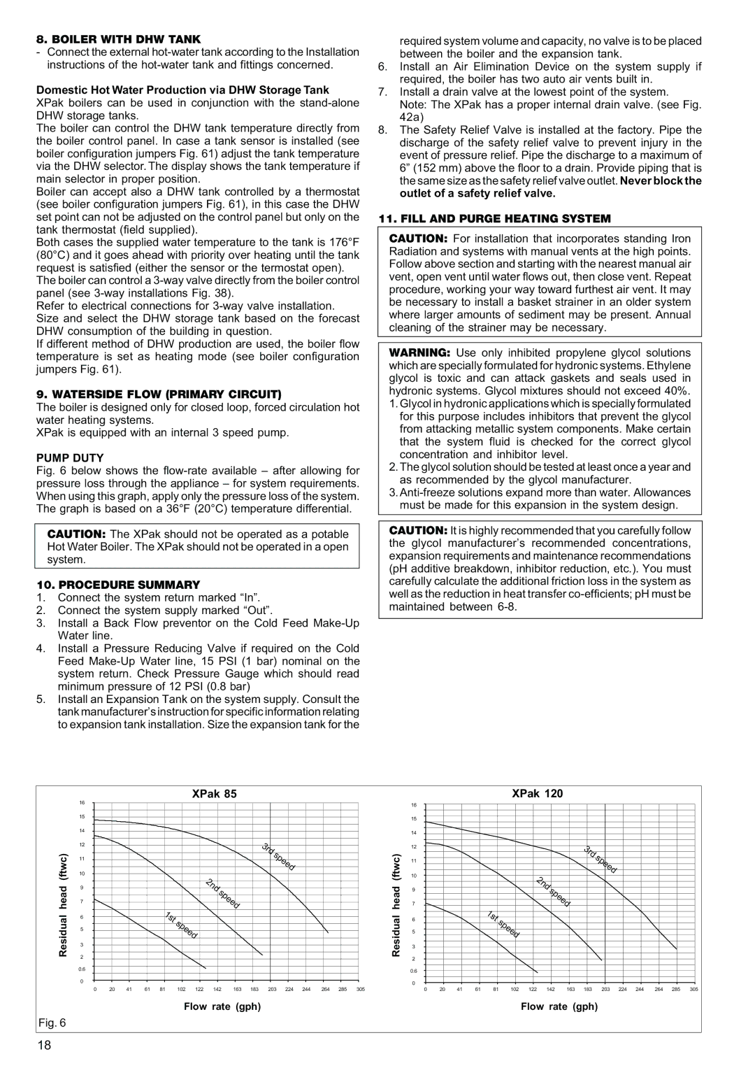
XPak is equipped with an internal 3 speed pump.

PUMP DUTY

Fig. 6 below shows the flow-rate available – after allowing for pressure loss through the appliance – for system requirements. When using this graph, apply only the pressure loss of the system. The graph is based on a 36°F (20°C) temperature differential.

CAUTION: The XPak should not be operated as a potable Hot Water Boiler. The XPak should not be operated in a open system.

10. PROCEDURE SUMMARY

1.Connect the system return marked “In”.

2.Connect the system supply marked “Out”.

3.Install a Back Flow preventor on the Cold Feed Make-Up Water line.

4.Install a Pressure Reducing Valve if required on the Cold Feed Make-Up Water line, 15 PSI (1 bar) nominal on the system return. Check Pressure Gauge which should read minimum pressure of 12 PSI (0.8 bar)

5.Install an Expansion Tank on the system supply. Consult the tank manufacturer’s instruction for specific information relating to expansion tank installation. Size the expansion tank for the

required system volume and capacity, no valve is to be placed between the boiler and the expansion tank.

6.Install an Air Elimination Device on the system supply if required, the boiler has two auto air vents built in.

7.Install a drain valve at the lowest point of the system. Note: The XPak has a proper internal drain valve. (see Fig. 42a)

8.The Safety Relief Valve is installed at the factory. Pipe the discharge of the safety relief valve to prevent injury in the event of pressure relief. Pipe the discharge to a maximum of 6” (152 mm) above the floor to a drain. Provide piping that is the same size as the safety relief valve outlet. Never block the outlet of a safety relief valve.

11. FILL AND PURGE HEATING SYSTEM

CAUTION: For installation that incorporates standing Iron Radiation and systems with manual vents at the high points. Follow above section and starting with the nearest manual air vent, open vent until water flows out, then close vent. Repeat procedure, working your way toward furthest air vent. It may be necessary to install a basket strainer in an older system where larger amounts of sediment may be present. Annual cleaning of the strainer may be necessary.

WARNING: Use only inhibited propylene glycol solutions which are specially formulated for hydronic systems. Ethylene glycol is toxic and can attack gaskets and seals used in hydronic systems. Glycol mixtures should not exceed 40%.

1.Glycol in hydronic applications which is specially formulated for this purpose includes inhibitors that prevent the glycol from attacking metallic system components. Make certain that the system fluid is checked for the correct glycol concentration and inhibitor level.

2.The glycol solution should be tested at least once a year and as recommended by the glycol manufacturer.

3.Anti-freeze solutions expand more than water. Allowances must be made for this expansion in the system design.

CAUTION: It is highly recommended that you carefully follow the glycol manufacturer’s recommended concentrations, expansion requirements and maintenance recommendations (pH additive breakdown, inhibitor reduction, etc.). You must carefully calculate the additional friction loss in the system as well as the reduction in heat transfer co-efficients; pH must be maintained between 6-8.


16


XPak 85


16


XPak 120


15


15


14


14


12


3rd


12


3rd


(ftwc)


speed


(ftwc)


11


11


speed


10


10


2nd


2nd


head

9


speed


head

9


speed


7


7


1st


1st


Residual

6


speed


Residual

6


speed


5


5


3


3


2


2


0.6


0.6


0


0


0

20

41

61

81

102

122

142

163

183

203

224

244

264

285

305


0

20

41

61

81

102

122

142

163

183

203

224

244

264

285

305


Flow rate (gph)


Flow rate (gph)


Fig. 6


18


Page 18
Image 18
Raypak 85, 120 manual Boiler With Dhw Tank, Waterside Flow Primary Circuit, Pump Duty, Procedure Summary, XPak