User’s Manual
Dual Channel High Power Digital Motor Controller
AX3500
Version 1.9b. June 1
AX3500 Motor Controller User’s Manual
Revision History
Revision History
Date
Version
Version 1.9b. June 1
Revision History
General Operation
SECTION
SECTION
SECTION
SECTION
SECTION
SECTION
Programming using built-in Switches and Display
Version 1.9b. June 1
Avoid Shorts when Mounting Board against Chassis
Important Safety
Do not Connect to a RC Radio with a Battery Attached
Warnings
Important Safety Warnings
AX3500
Locating the Switches and Connectors
Quick Start
What you will need
AX3500 Quick Start
Connecting to the Batteries and Motors
Connecting to the Batteries and Motors
Important Warning
Connecting to the 15-pin Connector
Signal
RC Mode
Connecting the R/C Radio
Connecting the R/C Radio
Powering On the Controller
Function
Button Operation
Prog and Set button status
Default Controller Configuration
Default Controller Configuration
Default Values
Parameter
Connecting the controller to your PC using Roborun
Obtaining the Controller’s Software Revision Number
Obtaining the Controller’s Software Revision Number
= Software version 1.9b
Exploring further
Product Description
SECTION 3AX3500 Motor Controller Overview
Multiple Command Modes
Technical features
Automatic Joystick Command Corrections
AX3500 Motor Controller Overview
Low Power Consumption
Technical features
High Efficiency Motor Power Outputs
Optical Encoder Inputs
Compact Open Frame PCB Design
Advanced Safety Features
Data Logging Capabilities
Power Connections
Connecting Power and Motors to the Controller
Power Connections
Connecting Power and Motors to the Controller
Controller Power
Power Control input is
Controller Power
And Main Battery
mended Off Configuration
Powering the Controller from a single Battery
Controller Powering Schemes
Controller Powering Schemes
Powering the Controller Using a Main and Backup Battery
Connecting the Motors
Single Channel Operation
Single Channel Operation
Converting the AX3500 to Single Channel
Power Fuses
Power Regeneration Considerations
Wire Length Limits
Electrical Noise Reduction Techniques
Wire Length Limits
Undervoltage Protection
Overvoltage Protection
Using the Controller with a Power Supply
Using the Controller with a Power Supply
Version 1.9b. June 1
General Operation
Input Command Modes
Basic Operation
Basic Operation
Open Loop, Separate Speed Control
Selecting the Motor Control Modes
Open Loop, Mixed Speed Control
General Operation
Selecting the Motor Control Modes
Closed Loop Speed Control
Close Loop Position Control
Temperature-Based Current Limitation
User Selected Current Limit Settings
Position Feedback Position Sensor Gear box
Setting
Battery Current vs. Motor Current
Battery Current vs. Motor Current
Motor Current = Battery Current / PWM ratio
Temperature
Motor Current = Battery Current / PWM Ratio
Regeneration Current Limiting
Setting Using
Programmable Acceleration
Switches
Programmable Acceleration
15 Hex
Command Control Curves
17.97%
0.089 second
Left / Right Tuning Adjustment
Left / Right Tuning Adjustment
Exponentiation Parameter Value
Selected Curve
Parameter Value
Speed Adjustment
Emergency Stop using External Switch
Emergency Shut Down Using Controller Switches
Activating Brake Release or Separate Motor Excitation
Activating Brake Release or Separate Motor Excitation
Using the Inputs to Activate the Buffered Output
Special Use of Accessory Digital Inputs
Using the Inputs to turn Off/On the Power MOSFET transistors
Inverted Operation
Self-Test Mode
Self-Test Mode
Encoder Speed or Position
AX3500 Connections
Connecting Sensors and Actuators to Input/Outputs
AX3500 Connections
Connecting Sensors and Actuators to Input/Outputs
AX3500’s Inputs and Outputs
Activated
AX3500’s Inputs and Outputs
I/O type
I/O List and Pin Assignment
Pin1
Signal depending
Input or
Connecting devices to Output C
Connecting devices to Output C
Important warning
Connecting Switches or Devices to Input F
Connecting Switches or Devices to EStop/Invert Input
Connecting Switches or Devices to EStop/Invert Input
Analog Inputs
Connecting Position Potentiometers to Analog Inputs
Connecting Tachometer to Analog Inputs
Connecting Tachometer to Analog Inputs
Ana2
Operating Mode
Ana2 p10
Ana 1 p11
Ana 3 p12
Ana 4 p8
Connecting External Thermistor to Analog Inputs
Connecting External Thermistor to Analog Inputs
Temp oC
Resistance kOhm
Using the Analog Inputs to Monitor External Voltages
Internal Voltage Monitoring Sensors
Connecting User Devices to Analog Inputs
Internal Heatsink Temperature Sensors
Connecting User Devices to Analog Inputs
Analog
Temperature Conversion C Source Code
Value
else
Internal Heatsink Temperature Sensors
LoTemp = i * 5
HiTemp = LoTemp + 5 lobound = TempTablei hibound = TempTablei+1
Version 1.9b. June 1
RC Pulse Output Overview
RC Pulses Output
RC Pulse Output Overview
Connecting Servos to Controllers
Connector Location and Pinout
Servo Connection to RevA Controllers
RC Pulses Output
Connecting to Slave Controllers
Connecting to Slave Controllers
Servo Connection to RevB Controllers
Command Value
Pulse Timing Information
Pulse Width 1.00ms
1.50ms
RC Channel Testing Using the PC Utility
RC Channel Testing Using the PC Utility
Version 1.9b. June 1
Optical Incremental Encoders Overview
Connecting and Using the Encoder Function
Optical Incremental Encoders Overview
Connecting and Using the Encoder Function
Recommended Encoder Types
Pulse Frequency in Hz = RPM / 60 * PPR
Connecting the Encoder
Connecting the Encoder
Motor - Encoder Polarity Matching
Cable Length and Noise Considerations
Name
Cable Color
Voltage Levels, Thresholds and Limit Switches
Voltage Levels, Thresholds and Limit Switches
Wiring Optional Limit Switches
Effect of Limit Switches
Wiring Limit Switches Without Encoders
Wiring Limit Switches Without Encoders
Motor 1 Fwd
Using the Encoder to Measure Speed
Using the Encoder Module to Measure Distance
Motor 2 Fwd
Motor 2 Rev
Using the Encoder to Track Position
Using the Encoder to Track Position
Important Notice
Distance = Destination - Counter value / Divider
The actual formula is as follows
RS232 Communication with the Encoder Module
Encoder Testing and Setting Using the PC Utility
RS232 Communication with the Encoder Module
Version 1.9b. June 1
Mode Description
Closed Loop Position Mode
Selecting the Position Mode
Mode Description
Sensor Mounting
Position Sensor Selection
Position Feedback Position Sensor Gear box
Closed Loop Position Mode
Feedback Potentiometer wiring
Feedback Potentiometer wiring
Feedback Potentiometer wiring in RC or RS232 Mode
Feedback Potentiometer wiring in Analog Mode
Feedback Wiring in Analog Mode on Single Channel Controllers
Feedback Wiring in RC or RS232 Mode on Single Channel Controllers
Analog Feedback on Single Channel Controllers
Analog Feedback on Single Channel Controllers
Sensor and Motor Polarity
Using Optical Encoders in Position Mode
Encoder Error Detection and Protection
Important Safety Warning
Adding Safety Limit Switches
Encoder Error Detection and Protection
FIGURE 62. Safety limit switches interrupting power to motors
Using Current Limiting as Protection
Using Current Limiting as Protection
Control Loop Description
PID tuning in Position Mode
Applied Power = Command Value - Actual Position * Proportional Gain
PID tuning in Position Mode
Version 1.9b. June 1
Selecting the Speed Mode
Closed Loop Speed Mode
Tachometer wiring
Using Optical Encoder for Speed FeedbackDigital Optical Encod
Tachometer or Encoder Mounting
Closed Loop Speed Mode
Speed Sensor and Motor Polarity
Speed Sensor and Motor Polarity
Adjust Offset and Max Speed
PID tuning in Speed Mode
PID tuning in Speed Mode
In Speed Mode, the Integral component of the PID is the most important and must be set first. The Proportional and Differential component will help improve the response time and loop stability
Use of the LED Display
Normal and Fault Condition LED Messages
Use of the LED Display
Normal and Fault Condition LED Messages
Motor Direction Status
Possible Display
Motor
No Control
Fault Messages
Fault Messages
Rapidly Flashing
Self-Test Display
Temporary Faults
Permanent Faults
Self-Test Display
= Software version 1.9b
Version 1.9b. June 1
SECTION 12 R/C Operation
Selecting the R/C Input Mode
Connector I/O Pin Assignment R/C Mode
Pin1
R/C Operation
R/C Input Circuit Description
R/C Input Circuit Description
Supplied Cable Description
FIGURE 75. RC connection cable
Powering the Radio from the controller
FIGURE 74. RC Cable wiring diagram
Powering the Radio from the controller
Operating the Controller in R/C mode
Connecting to a Separately Powered Radio
Reception Watchdog
Reception Watchdog
R/C Transmitter/Receiver Quality Considerations
Important Notice about PCM Radios
Joystick Deadband Programming
Joystick Deadband Programming
Deadband Parameter Value
Deadband as Percent of full Joystick Travel
Joystick Calibration
Left/Right Tuning Adjustment
Automatic Joystick Calibration
Automatic Joystick Calibration
On before entering joystick calibration
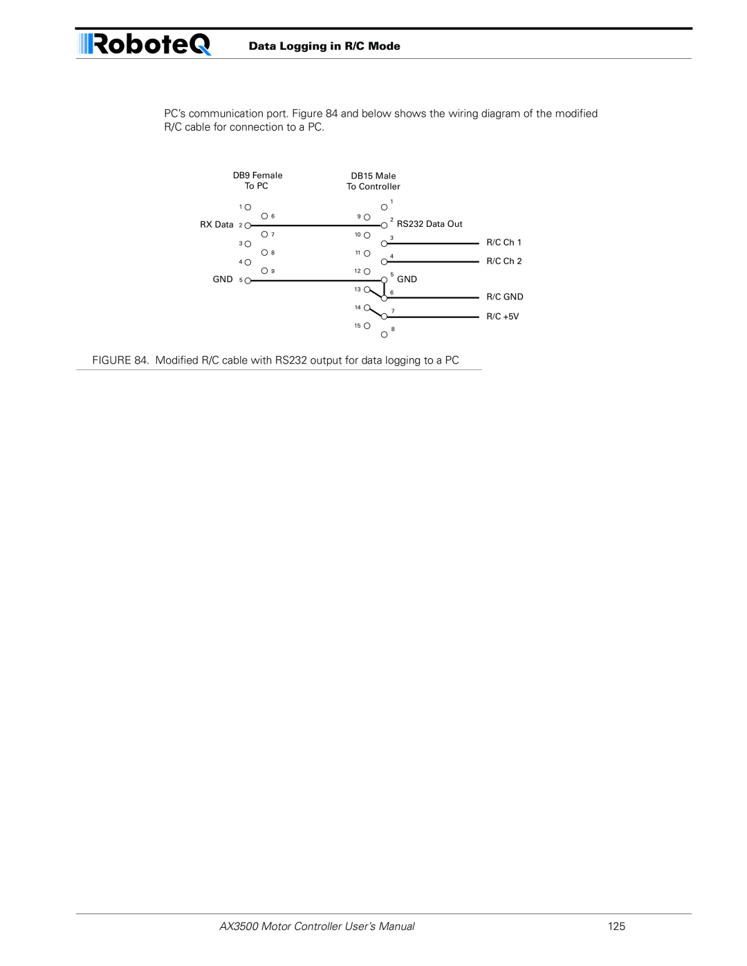
Data Logging in R/C Mode
To Controller
Data Logging in R/C Mode
DB15 Male
Version 1.9b. June 1
Analog Control and Operation
Analog Control and Operation
Connector I/O Pin Assignment Analog Mode
Connecting to a Voltage Source
Connecting to a Voltage Source
Connecting a Potentiometer
Selecting the Potentiometer Value
Analog Deadband Adjustment
Under Voltage Safety
Power-On Safety
Data Logging in Analog Mode
Motor Power at 0%
Data Logging in Analog Mode
Version 1.9b. June 1
Use and benefits of RS232
Serial RS-232 Controls and Operation
Use and benefits of RS232
Serial RS-232 Controls and Operation
Connector I/O Pin Assignment RS232 Mode
Cable configuration
Cable configuration
Extending the RS232 Cable
Establishing Manual Communication with a PC
Communication Settings
9600 bits/s, 7-bit data, 1 Start bit, 1 Stop bit, Even Parity
Roboteq v1.9b 06/01/07 s
RS232 Communication with the Encoder Module
Establishing Manual Communication with a PC
Data Logging String in R/C or Analog mode
Entering RS232 from R/C or Analog mode
RS232 Mode if default
Commands Acknowledge and Error Messages
Command Acknowledgement
Command Error
RS-232 Watchdog
Controller Commands and Queries
Command
Type
Set Accessory Output
Set Motor Command Value
Query Power Applied to Motors
Controller Commands and Queries
Syntax
Query Amps from Battery to each Motor Channel
Query Heatsink Temperatures
Query Analog Inputs
?r or ?R
?m or ?M
Reset Controller
Query Battery Voltages
Query Digital Inputs
Examples
Apply Parameter Changes
Accessing & Changing Configuration Parameter in Flash
Accessing & Changing Configuration Parameter in Flash
Read parameter
Active after
Flash Configuration Parameters List
Location
Motor Control Mode
Input Control Mode
Access
After Reset
Definition
Amps Limit
Acceleration
Input Switches Function
RC Joystick or Analog Deadband
Left/Right Adjust
Exponentiation on Channel 1 and Channel
08 - Channel
Default Encoder Distance Divider
Default Encoder Time Base 1 and
0B - Encoder
0C - Encoder
Joystick Min, Max and Center Values
Default PID Gains
0F - Proportional Gain
10 - Integral Gain
Reading & Changing Operating Parameters at Runtime
Reading & Changing Operating Parameters at Runtime
Read/Change PID Values
Operating Modes Registers
Access Read/Write Effective Instantly
80 - Channel
Controller Status Register
PWM Frequency Register
Address Access Read/Write Effective Instantly
Fault Condition
Current Amps Limit Registers
Controller Identification Register
Model or Function
8B - Channel
Set/Reset Encoder Counters and Destination Registers
RS232 Encoder Command Set
Read Encoder Counter
RS232 Encoder Command Set
q or !Q n
Read Speed
7 Set Encoder 1 destination register with value in buffer
8 Set Encoder 2 destination register with value in buffer
Read Speed/Distance
Read Encoder Limit Switch Status
Read Distance
Read / Modify Encoder Module Registers and Parameters
Important Note
Switch
n Value
Size
Parameter Description
Register Description
Switch Status
Encoder Hardware ID code
Address *84
Counter Read/Write Mailbox
Speed or Distance 1 or
Counter 1 and
Destination Register 1 and
Speed 1 and
Distance 1 and
Time Base 1 and
Encoder Threshold
RC Pulse Outputs Activation
Counter Read Data Format
Default Value
Counter Read Data Format
Controller Output
Decimal
32-bit Hex
Automatic Switching from RS232 to RC Mode
Automatic Switching from RS232 to RC Mode
Data Logging Cables
00 11 22 33 44 55 66 77 88 99 AA BB CC
Analog and R/C Modes Data Logging String Format
Decimal to Hexadecimal Conversion Table
Decimal to Hexadecimal Conversion Table
AX3500 Motor Controller User’s Manual
AX3500 Motor Controller User’s Manual
Decimal to Hexadecimal Conversion Table
Version 1.9b. June 1
Programming Methods
SECTION 15 Configuring the Controller using the Switches
Programming using built-in Switches and Display
Program
Entering Programming Mode
Configuring the Controller using the Switches
Programming using built-in Switches and Display
Changing parameters
The Special Case of Joystick Calibration
Exiting the Parameter Setting Mode
Restoring factory defaults
Programmable Parameters List
This manual is for software version 1.9b
For safety reasons, the modes below
Possible Values default
cannot be selected using the switches
Programmable Parameters List
Possible Values default
System Requirements
SECTION 16 Using the Roborun Configuration Utility
Downloading and Installing the Utility
Using the Roborun Configuration Utility
Connecting the Controller to the PC
Roborun Frame, Tab and Menu Descriptions
Roborun Frame, Tab and Menu Descriptions
1- Program Revision Number
2- Controller and Communication Link Information
3- Parameter Selection and Setting and Special Functions
Getting On-Screen Help
4- File and Program Management Commands
5- View Controller Connector Pinout
Loading, Changing Controller Parameters
Control Settings
Loading, Changing Controller Parameters
1- Controller Input
3- Input Command Adjustment
Power Settings
4- Emergency Stop or Invert Switch Select
5- Effect of Digital Inputs
Loading, Changing Controller Parameters 2- Left/Right Adjust
Analog or R/C Specific Settings
3- Acceleration Setting
1- Deadband
Closed Loop Parameters
Encoder Setting and Testing
Encoder Setting and Testing
Encoder Module Parameters Setting
Viewing Encoder Data
RC Output Testing
Exercising the Motors
Running the Motors
Running the Motors
3- Measurement
2- Motor Power setting
1- Run/Stop Button
5- Transmit and Receive Data
4- Real-Time Strip Chart Recorder
6- Input Status and Output Setting
7- Data Logging and Timer
Logging Data to Disk
8- Joystick Enable
4- Reset Timer button
Parameter Header
Connecting a Joystick
Data type/range
Measured Parameter
1- Terminal Screen
Using the Console
2- Command Entry
Loading and Saving Profiles to Disk
Viewing and Logging Data in Analog and R/C Modes
4- Send Reset String
Viewing and Logging Data in Analog and R/C Modes
Operating the AX3500 over a Wired or Wireless LAN
Updating the Controller’s Software
Updating the Controller’s Software
Updating the Encoder Software
Creating Customized Object Files
Creating Customized Object Files
Version 1.9b. June 1
Mechanical Dimensions
Mechanical Specifications
Mechanical Dimensions
Mechanical Specifications
Mounting Considerations
Thermal Considerations
Attaching the Controller Directly to a Chassis
Attaching the Controller Directly to a Chassis
Precautions to observe
Wire Dimensions
Wire Dimensions
Weight
Version 1.9b. June 1
Mechanical Specifications
AX3500 Motor Controller User’s Manual