Unit 3: Installation
|
| RS232C SERIAL INTERFACE SIGNALS |
PIN | DIRECTION | SIGNAL DEFINITION |
1 | Reference | FG (Frame Ground) |
2 | To Host | TD (Transmit Data) - Data from the printer to the host computer. Sends |
|
| |
3 | To Printer | RD (Receive Data) - Data to the printer from the host computer. |
4 | To Host | RTS (Request to Send) - Used with Ready/Busy flow control to indicate an |
|
| error condition. RTS is high and remains high unless the print head is open (in |
|
| this case, RTS would return to the high state after the print head is closed and |
|
| the printer is placed back |
|
| (e.g., ribbon out, label out). |
5 | To Printer | CTS (Clear to Send) - When this line is high, the printer assumes that data is |
|
| ready to be transmitted. The printer will not receive data when this line is low. If |
|
| this line is not being used, it should be tied high (to pin 4). |
6 | To Printer | DSR (Data Set Ready) - When this line is high, the printer will be ready to |
|
| receive data. This line must be high before data is transmitted. If this line is not |
|
| being used, it should be tied high (to pin 20). |
7 | Reference | SG (Signal Ground) |
20 | To Host | DTR (Data Terminally Ready) - This signal applies to Ready/Busy flow control. |
|
| The printer is ready to receive data when this pin is high. It goes low when the |
|
| printer is |
|
| printing in the single job buffer mode. It will also go low when the data in the |
|
| buffer reaches the buffer near full level. |
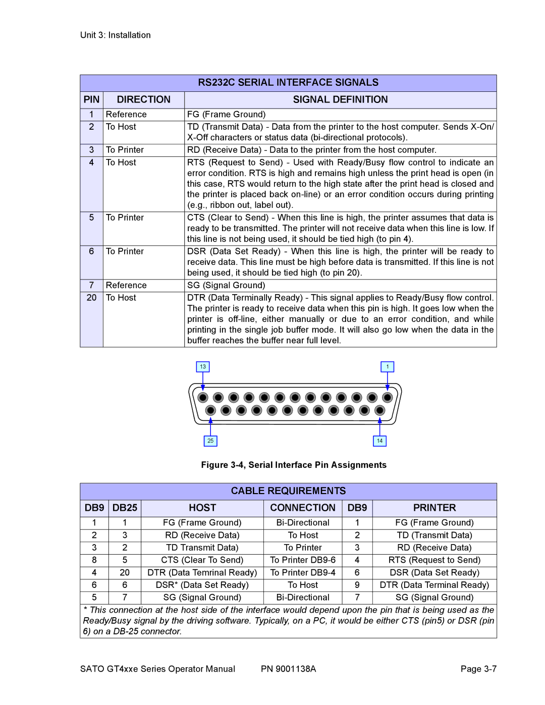
13
1
25
14
Figure 3-4, Serial Interface Pin Assignments
CABLE REQUIREMENTS
DB9 | DB25 | HOST | CONNECTION | DB9 | PRINTER |
1 | 1 | FG (Frame Ground) | 1 | FG (Frame Ground) | |
2 | 3 | RD (Receive Data) | To Host | 2 | TD (Transmit Data) |
3 | 2 | TD Transmit Data) | To Printer | 3 | RD (Receive Data) |
8 | 5 | CTS (Clear To Send) | To Printer | 4 | RTS (Request to Send) |
4 | 20 | DTR (Data Temrinal Ready) | To Printer | 6 | DSR (Data Set Ready) |
6 | 6 | DSR* (Data Set Ready) | To Host | 9 | DTR (Data Terminal Ready) |
5 | 7 | SG (Signal Ground) | 7 | SG (Signal Ground) |
* This connection at the host side of the interface would depend upon the pin that is being used as the Ready/Busy signal by the driving software. Typically, on a PC, it would be either CTS (pin5) or DSR (pin 6) on a
SATO GT4xxe Series Operator Manual | PN 9001138A | Page |