Unit 6: Maintenance
REPLACEMENT PROCEDURES
This unit contains
PRINT HEAD REPLACEMENT
If the print head becomes damaged or worn, it can be easily removed and replaced without having to make critical adjustments.
1Switch off the printer and disconnect the power supply cord.
2 Open the top housing cover.
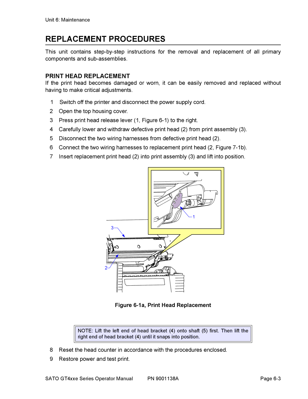
3 Press print head release lever (1, Figure
4 Carefully lower and withdraw defective print head (2) from print assembly (3). 5 Disconnect the two wiring harnesses from defective print head (2).
6 Connect the two wiring harnesses to replacement print head (2, Figure
3
1 |
2![]()
Figure 6-1a, Print Head Replacement
NOTE: Lift the left end of head bracket (4) onto shaft (5) first. Then lift the right end of head bracket (4) until it snaps into position.
8Reset the head counter in accordance with the procedures enclosed.
9Restore power and test print.
SATO GT4xxe Series Operator Manual | PN 9001138A | Page |