Page 108 SITRANS LC 500 – INSTRUCTION MANUAL
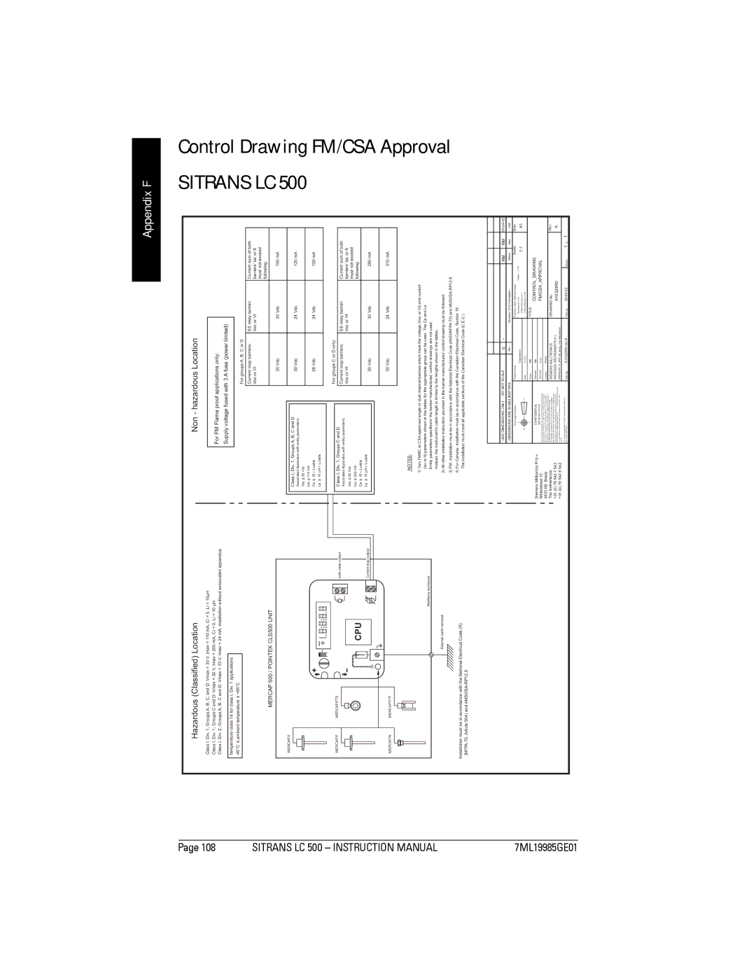
Hazardous (Classified) Location
Class I, Div. 1, Groups A, B, C, and D: Vmax = 30 V, Imax = 110 mA, Ci = 0, Li = 10µH
Class I, Div. 1, Groups C and D: Vmax = 30 V, Imax = 200 mA, Ci = 0, Li = 10 µH
Class I, Div. 2, Groups A, B, C and D: Vmax = 33 V, Imax = 24 mA, installation without associated apparatus.
Temperature class T4 for class I, Div. 1 applications
MERCAP 500 / POINTEK CLS500 UNIT
MERCAP/2 |
|
MERCAP/F | MERCAP/FTS |
| solid state output |
| CPU |
| Current loop output |
MERCAP/N | MERCAP/FTF |
| Merflame enclosure |
External earth terminal
Installation must be in accordance with the National Electrical Code (R) (NFPA 70, Article 504) and
Appendix F
|
|
|
| Non - hazardous Location |
|
|
| SITRANSLC500 | ControlDrawing | |||
|
|
|
|
|
|
|
|
|
| |||
|
|
|
| For FM Flame proof applications only: |
|
|
|
|
| |||
|
|
|
| Supply voltage fused with 3 A fuse (power limited) |
|
|
|
| ||||
|
|
|
|
|
|
|
|
|
|
|
|
|
|
|
|
|
|
|
| For groups A, B, C or D |
|
|
|
|
|
|
|
|
|
|
|
|
|
|
|
|
|
|
|
|
|
|
|
|
| Current loop barriers: | SS relay barrier: | Current sum of both |
|
| |
|
|
|
|
|
|
| Voc or Vt | Voc or Vt | barriers' Isc or It |
|
| |
|
|
|
|
|
|
|
|
|
| must not exceed |
|
|
|
|
|
|
|
|
|
|
|
| following: |
|
|
|
|
|
|
|
|
|
|
|
|
|
|
|
|
|
|
|
|
|
| 30 Vdc | 30 Vdc | 100 mA |
|
| |
|
|
|
|
|
|
|
|
|
|
|
|
|
|
|
| Class I, Div. 1, Groups A, B, C and D |
|
| 30 Vdc | 24 Vdc | 120 mA |
|
| ||
|
|
| Associated Apparatus with entity parameters: |
|
|
|
| |||||
|
|
|
|
|
|
|
|
|
|
| ||
|
|
| Voc < 30 Vdc |
|
|
|
|
|
|
|
| |
|
|
| Lsc < 110 mA |
|
|
|
|
|
|
| FM/CSA | |
|
|
| Ca < Ø + Lcable |
|
| 26 Vdc | 24 Vdc | 150 mA |
| |||
|
|
| La < 10 µH + Lcable |
|
|
|
|
|
|
|
| |
|
|
|
|
|
|
|
|
|
|
|
|
|
|
|
|
|
|
|
| For groups C or D only: |
|
|
|
|
|
|
|
|
|
|
|
|
|
|
|
|
| |
|
|
| Class I, Div. 1, Groups C and D |
|
| Current loop barriers: | SS relay barrier: | Current sum of both |
|
| ||
|
|
| Associated Apparatus with entity parameters: |
|
|
|
| |||||
|
|
|
|
| Voc or Vt | Voc or Vt | barriers' Isc or It |
|
| |||
|
|
| Voc < 30 Vdc |
|
|
|
| |||||
|
|
|
|
|
|
|
| must not exceed |
|
| ||
|
|
| Lsc < 200 mA |
|
|
|
|
|
|
| ||
|
|
|
|
|
|
|
| following: |
|
| ||
|
|
|
|
|
|
|
|
|
|
|
| |
|
|
| Ca < Ø + Lcable |
|
|
|
|
|
|
|
| |
|
|
| La < 10 µH + Lcable |
|
| 30 Vdc | 30 Vdc | 260 mA |
|
| ||
|
|
|
|
|
|
|
|
|
| Approval | ||
|
|
| 3) FM: Installation must be in accordance with the | National Electrical Code (ANSI/NFPA 70) and | 310 mA |
| ||||||
|
|
|
|
|
|
| 30 Vdc | 24 Vdc |
|
| ||
NOTES:
1) Two FMRC or CSA approved single or dual channel barriers which meet the voltage (Voc or Vt) and current (Isc or It) parameters shown in the tables for the appropriate group can be used. The Ca and La
Entity parameters specified in the barrier manufactures' control drawings are not used.
Instead, the instrument's cable length is limited to the lengths shown in the tables.
2) All other installation instruction provided in the barrier manufactures' control drawing must be followed.
4) For Canada: Installation must be in accordance with the Canadian Electrical Code, Section 18. The installation must meet all applicable sections of the Canadian Electrical Code (C.E.C.)
7ML19985GE01
Siemens Milltronics PI b.v. Nikkelstraat 10
4823 AB Breda
The Netherlands
+31 (0) 76 542 7 542
+31 (0) 76 542 8 542
|
|
|
|
|
|
|
|
|
|
|
|
|
|
|
|
|
|
|
|
|
|
|
|
|
|
|
|
|
|
|
|
|
|
|
|
|
|
|
|
|
|
|
|
|
|
|
|
USE DIMENSIONS ONLY - DO NOT SCALE |
| 0 | - |
|
|
|
|
| RM |
|
| RM |
|
| |||||||||
DIMENSIONS ARE IN MILLIMETERS |
|
| Rev. |
| Revision / ECN Description |
|
| Drawn |
|
| Appr. |
| Date | ||||||||||
|
| Third Angle Projection | Product Group |
|
|
|
| Tolerance Unless Otherwise Noted: |
|
| Scale: |
|
| Size: | |||||||||
|
|
|
|
|
|
|
|
|
| Capacitance |
|
| No Decimal ± 0.5 | Angles: ± 0.5° | 1:1 |
| A1 | ||||||
|
|
|
|
|
|
|
|
|
|
|
|
|
| 1 Place Decimal ± 0.1 |
|
|
|
| |||||
|
|
|
|
|
|
|
|
| Date: |
|
|
| 2 Place Decimal ± 0.01 |
|
|
|
|
|
|
|
| ||
|
|
|
|
|
|
|
|
|
|
|
|
|
|
|
|
|
|
|
| ||||
|
|
|
|
|
|
|
|
| Drawn: | RM |
|
| TITLE: |
|
|
|
|
|
|
|
|
| |
|
| CONFIDENTIAL | Checked: | RM |
|
|
| CONTROL_DRAWING |
|
|
|
|
| ||||||||||
|
| IMPORTANT NOTICE | Approved: | CvG |
|
|
| FM/CSA_APPROVAL |
|
|
|
|
| ||||||||||
THIS DOCUMENT REMAINS THE PROPERTY OF SIEMENS MILLTRONICS |
|
|
|
|
|
|
|
|
| ||||||||||||||
AND IS SUBJECT TO RECALL. IT MAY NOT BE COPIED, AND IS ISSUED | Location: | Breda |
|
|
|
|
|
|
|
|
|
|
|
| |||||||||
AND CAN BE UTILIZED ONLY FOR SUCH LIMITED PURPOSES AS MAY |
|
|
|
|
|
|
|
|
|
|
|
| |||||||||||
SPECIFICALLY HAVE BEEN AUTHORIZED BY SIEMENS MILLTRONICS. IT |
|
|
|
|
|
|
|
|
|
|
|
|
|
|
| ||||||||
IS TO BE MAINTAINED CONFIDENTIAL, SINCE IT MAY CONTAIN | SIEMENS MILLTRONICS |
|
| DRAWING No: |
|
|
|
|
|
|
| Rev. | |||||||||||
PROPRIETARY INFORMATION AND TRADE SECRETS OF SIEMENS |
|
|
|
|
|
|
|
|
| ||||||||||||||
MILLTRONICS OR OTHERS. THE ITEM DEPICTED MAY THEMSELVES BE | PROCESS INSTRUMENTS b.v. |
|
| A10324R0 |
|
|
|
|
|
|
| A | |||||||||||
THE SUBJECT OF PATENTS, INDUSTRIAL DESIGN REGISTRATIONS OR |
|
|
|
|
|
|
|
|
| ||||||||||||||
COPYRIGHTS OF SIEMENS MILLTRONICS O | R OTHERS, AND THE ISSUE | Nikkelstraat 10, 4823 AB Breda, The Netherlands |
|
|
|
|
|
|
|
|
| ||||||||||||
OF THIS DRAWING DOES NOT IMPLY ANY LICENSE UNDER ANY SUCH |
|
|
|
|
|
|
|
|
|
|
| ||||||||||||
RIGHTS |
|
|
|
|
|
|
|
|
|
|
|
|
|
|
|
|
|
| |||||
COPYRIGHT SIEMENS MILLTRONICS PROCESS INSTRUMENTS b.v. | File No. | A10324R0.rev A |
|
|
| Sheet |
| 1 Of | 1 |
| |||||||||||||
ALL RIGHTS RESERVED |
|
|
|
| Plot at: |
|
|
| |||||||||||||||
|
|
|
|
|
|
|
|
|
|
|
|
|
|
|
|
|
|
|
|
|
|
|
|