Series | Table of Contents |
|
|
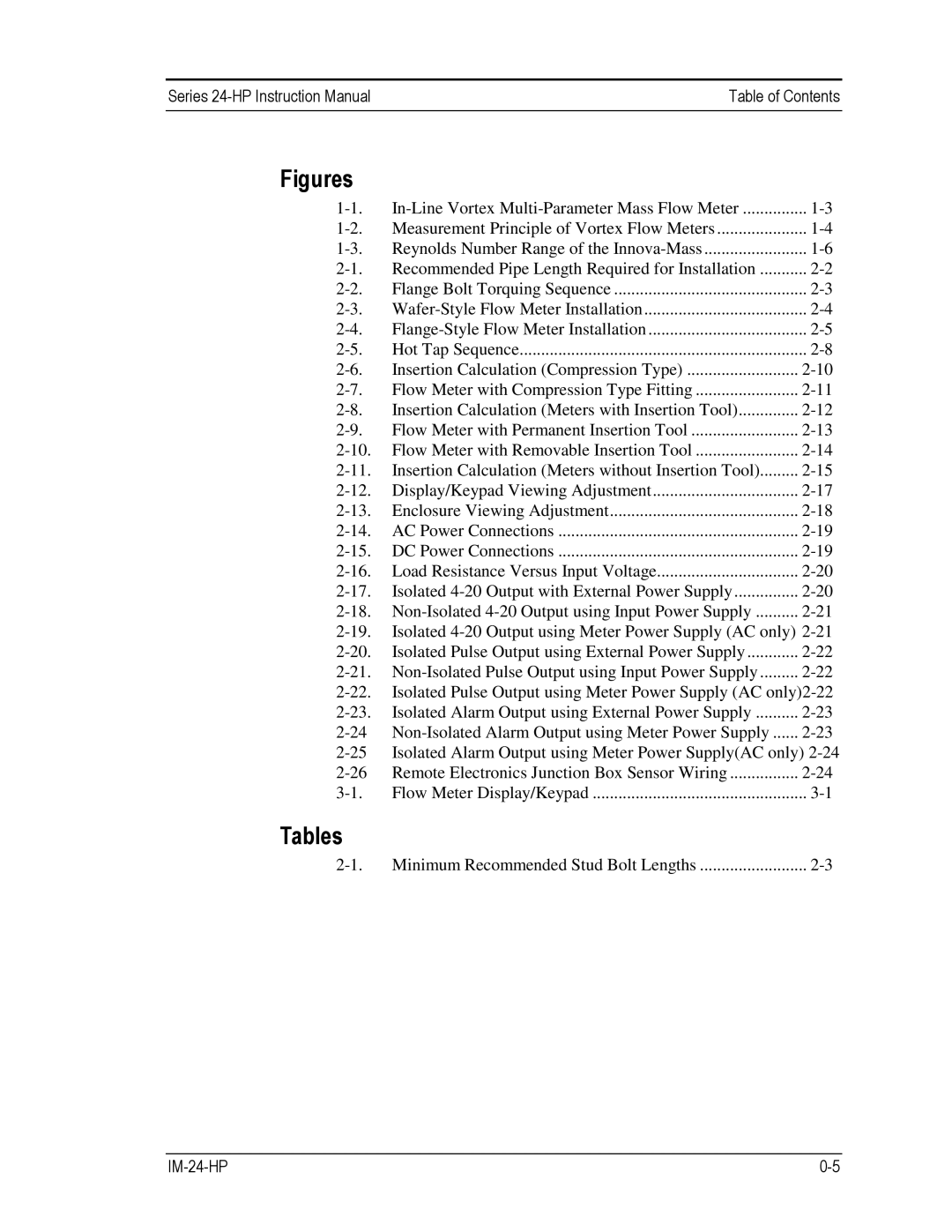
Figures
Measurement Principle of Vortex Flow Meters | ||
Reynolds Number Range of the | ||
Recommended Pipe Length Required for Installation | ||
Flange Bolt Torquing Sequence | ||
Hot Tap Sequence | ||
Insertion Calculation (Compression Type) | ||
Flow Meter with Compression Type Fitting | ||
Insertion Calculation (Meters with Insertion Tool) | ||
Flow Meter with Permanent Insertion Tool | ||
Flow Meter with Removable Insertion Tool | ||
Insertion Calculation (Meters without Insertion Tool) | ||
Display/Keypad Viewing Adjustment | ||
Enclosure Viewing Adjustment | ||
AC Power Connections | ||
DC Power Connections | ||
Load Resistance Versus Input Voltage | ||
Isolated | ||
Isolated | ||
Isolated Pulse Output using External Power Supply | ||
Isolated Pulse Output using Meter Power Supply (AC | ||
Isolated Alarm Output using External Power Supply | ||
Isolated Alarm Output using Meter Power Supply(AC only) | ||
Remote Electronics Junction Box Sensor Wiring | ||
Flow Meter Display/Keypad | ||
