Chapter 3 Operation | Series |
|
|
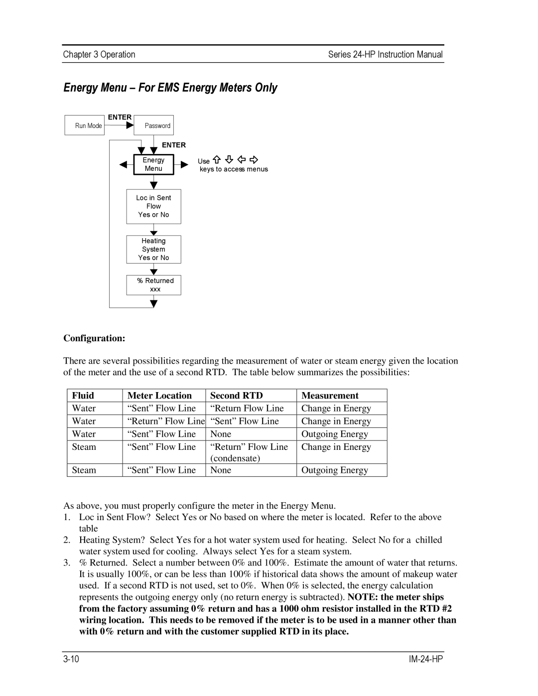
Energy Menu – For EMS Energy Meters Only
Run Mode
ENTER |
Password |
ENTER |
Energy |
Menu |
Loc in Sent |
Flow |
Yes or No |
Heating |
System |
Yes or No |
% Returned |
xxx |
Use ![]()
![]()
![]()
![]() keys to access menus
keys to access menus
Configuration:
There are several possibilities regarding the measurement of water or steam energy given the location of the meter and the use of a second RTD. The table below summarizes the possibilities:
Fluid | Meter Location | Second RTD |
Water | “Sent” Flow Line | “Return Flow Line |
Water | “Return” Flow Line | “Sent” Flow Line |
Water | “Sent” Flow Line | None |
Steam | “Sent” Flow Line | “Return” Flow Line |
|
| (condensate) |
Steam | “Sent” Flow Line | None |
|
|
|
Measurement
Change in Energy
Change in Energy
Outgoing Energy
Change in Energy
Outgoing Energy
As above, you must properly configure the meter in the Energy Menu.
1.Loc in Sent Flow? Select Yes or No based on where the meter is located. Refer to the above table
2.Heating System? Select Yes for a hot water system used for heating. Select No for a chilled water system used for cooling. Always select Yes for a steam system.
3.% Returned. Select a number between 0% and 100%. Estimate the amount of water that returns. It is usually 100%, or can be less than 100% if historical data shows the amount of makeup water used. If a second RTD is not used, set to 0%. When 0% is selected, the energy calculation represents the outgoing energy only (no return energy is subtracted). NOTE: the meter ships from the factory assuming 0% return and has a 1000 ohm resistor installed in the RTD #2 wiring location. This needs to be removed if the meter is to be used in a manner other than with 0% return and with the customer supplied RTD in its place.