Chapter 2 Installation | Series |
|
|
Installing Flow Meters with a Compression Connection*
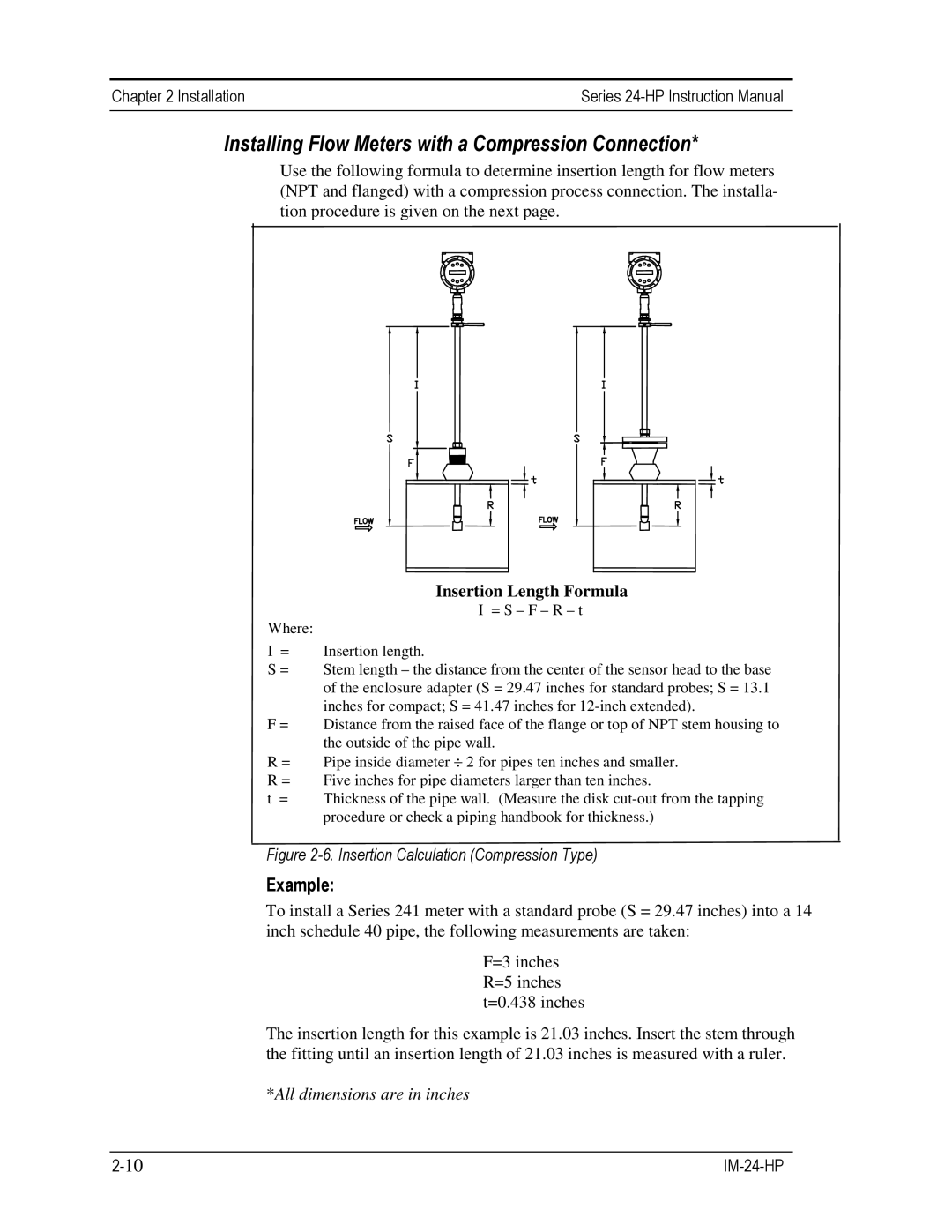
Use the following formula to determine insertion length for flow meters (NPT and flanged) with a compression process connection. The installa- tion procedure is given on the next page.
Insertion Length Formula
I = S – F – R – t
Where:
I = Insertion length.
S = Stem length – the distance from the center of the sensor head to the base of the enclosure adapter (S = 29.47 inches for standard probes; S = 13.1 inches for compact; S = 41.47 inches for
F = Distance from the raised face of the flange or top of NPT stem housing to the outside of the pipe wall.
R = Pipe inside diameter ⎟ 2 for pipes ten inches and smaller.
R = Five inches for pipe diameters larger than ten inches.
t = Thickness of the pipe wall. (Measure the disk
Figure 2-6. Insertion Calculation (Compression Type)
Example:
To install a Series 241 meter with a standard probe (S = 29.47 inches) into a 14 inch schedule 40 pipe, the following measurements are taken:
F=3 inches R=5 inches t=0.438 inches
The insertion length for this example is 21.03 inches. Insert the stem through the fitting until an insertion length of 21.03 inches is measured with a ruler.
*All dimensions are in inches