Chapter 2 Installation

Series 24-HP Instruction Manual

4-20 mA Output Connections

The standard Innova-Mass Flow Meter has a single 4-20 mA loop. Two additional loops are available on the optional communication board. The

4-20 mA loop current is controlled by the meter electronics. The electron- ics must be wired in series with the sense resistor or current meter. The current control electronics require 12 volts at the input terminals to oper- ate correctly.

The maximum loop resistance (load) for the current loop output is depend- ent upon the supply voltage and is given in Figure 2-16. The 4-20 mA loop is optically isolated from the flow meter electronics.

Rload is the total resistance in the loop, including the wiring resistance

(Rload = Rwire + Rsense ). To calculate Rmax, the maximum Rload for the loop, use the maximum loop current, 20 mA. The voltage drop in the loop due to resistance is 20 mA times Rload and this drop is subtracted from the in- put voltage. Thus:

The maximum resistance Rload = Rmax = 50 * (Vsupply – 12V).
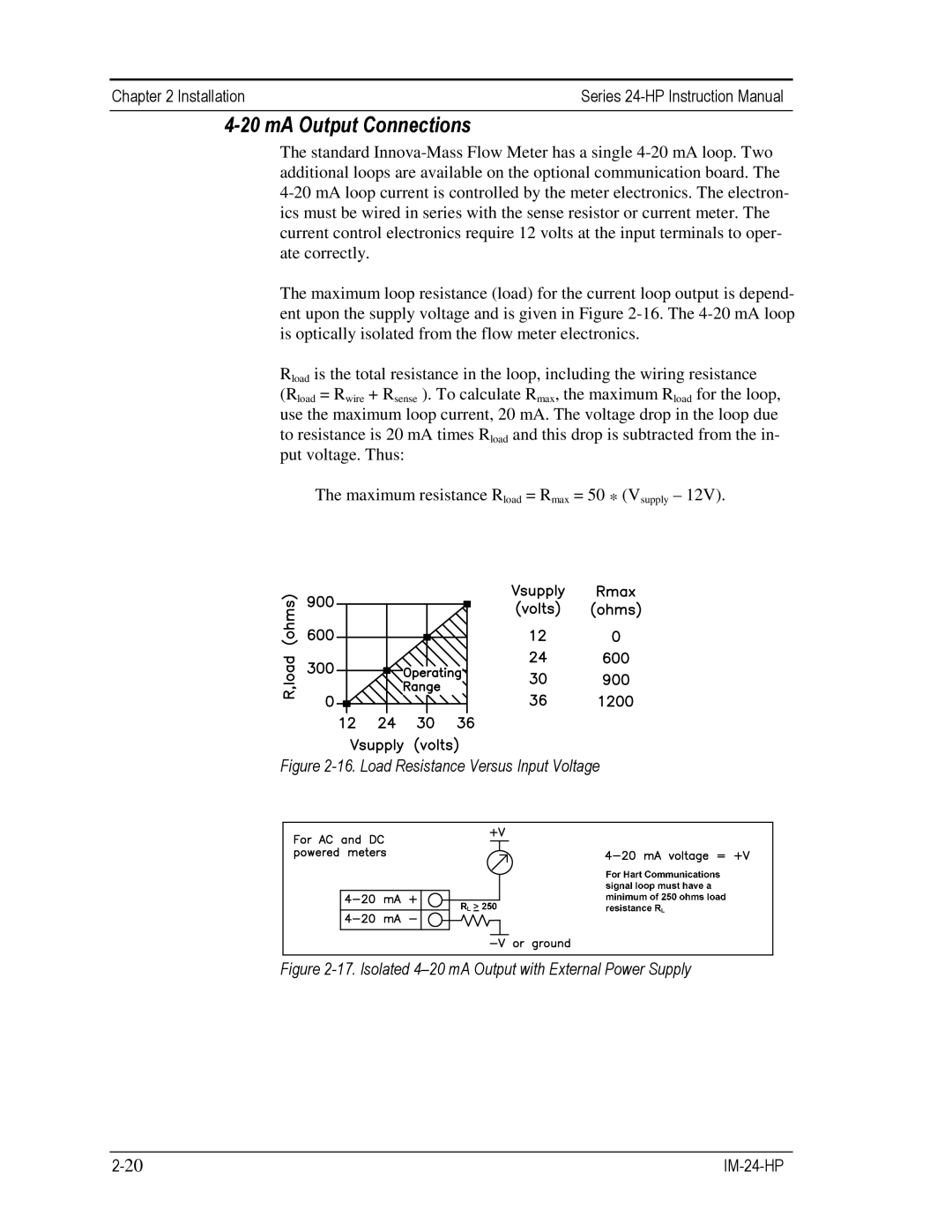
Figure 2-16. Load Resistance Versus Input Voltage

Figure 2-17. Isolated 4–20 mA Output with External Power Supply

2-20

IM-24-HP

Page 34
Image 34
Sierra 241-VTP, 240-VTP instruction manual MA Output Connections, Load Resistance Versus Input Voltage