Appendix A Specifications |
| Series | ||||
|
|
|
|
|
|
|
|
|
|
|
|
|
|
|
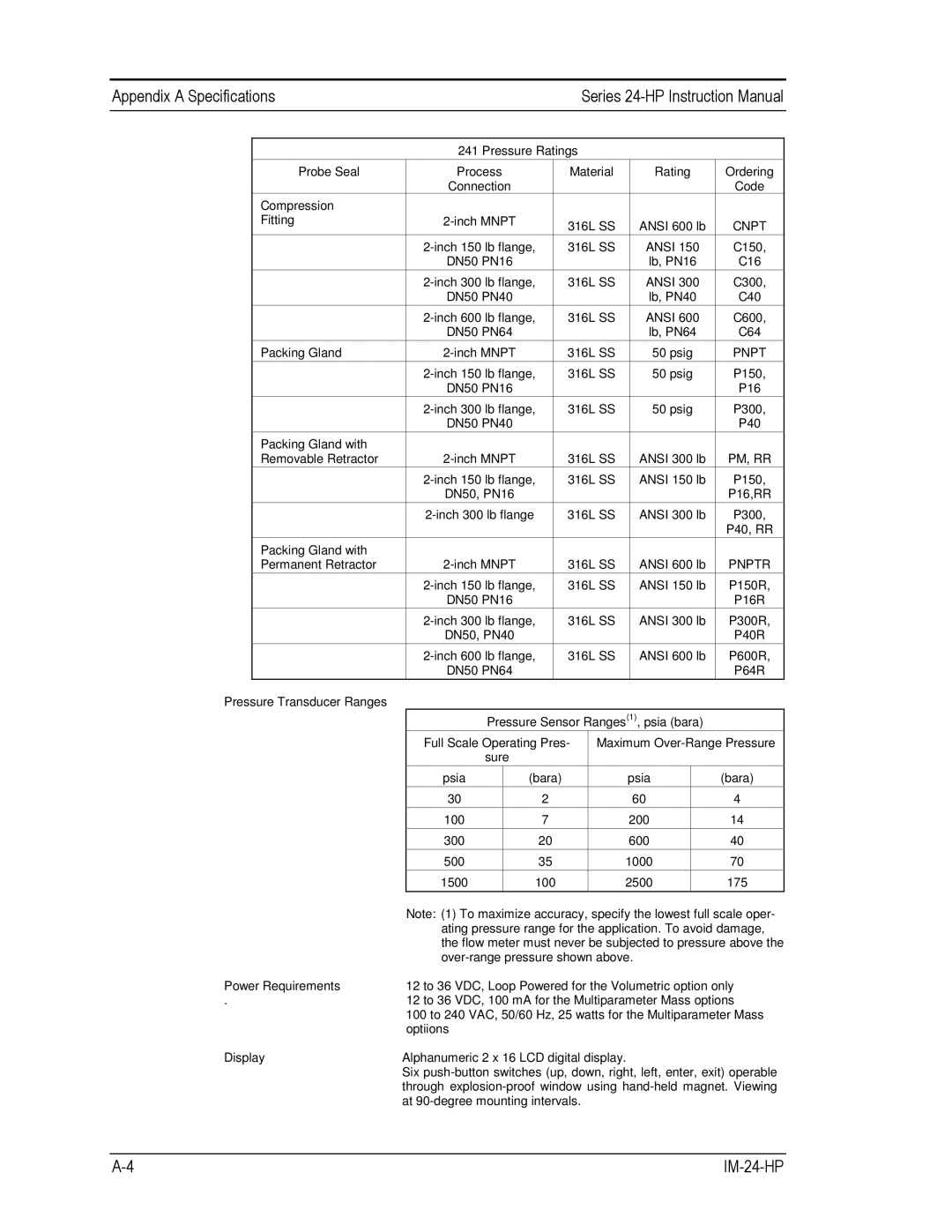
| 241 Pressure Ratings |
|
|
| |
| Probe Seal | Process | Material | Rating | Ordering |
|
|
| Connection |
|
| Code |
|
| Compression |
|
|
|
|
|
| Fitting | 316L SS | ANSI 600 lb | CNPT |
| |
|
|
|
| |||
|
| 316L SS | ANSI 150 | C150, |
| |
|
| DN50 PN16 |
| lb, PN16 | C16 |
|
|
| 316L SS | ANSI 300 | C300, |
| |
|
| DN50 PN40 |
| lb, PN40 | C40 |
|
|
| 316L SS | ANSI 600 | C600, |
| |
|
| DN50 PN64 |
| lb, PN64 | C64 |
|
|
|
|
|
|
|
|
| Packing Gland | 316L SS | 50 psig | PNPT |
| |
|
|
|
|
|
|
|
|
| 316L SS | 50 psig | P150, |
| |
|
| DN50 PN16 |
|
| P16 |
|
|
|
|
|
|
|
|
|
| 316L SS | 50 psig | P300, |
| |
|
| DN50 PN40 |
|
| P40 |
|
| Packing Gland with |
|
|
|
|
|
| Removable Retractor | 316L SS | ANSI 300 lb | PM, RR |
| |
|
| 316L SS | ANSI 150 lb | P150, |
| |
|
| DN50, PN16 |
|
| P16,RR |
|
|
|
|
|
|
|
|
|
| 316L SS | ANSI 300 lb | P300, |
| |
|
|
|
|
| P40, RR |
|
|
|
|
|
|
|
|
| Packing Gland with |
|
|
|
|
|
| Permanent Retractor | 316L SS | ANSI 600 lb | PNPTR |
| |
|
| 316L SS | ANSI 150 lb | P150R, |
| |
|
| DN50 PN16 |
|
| P16R |
|
|
| 316L SS | ANSI 300 lb | P300R, |
| |
|
| DN50, PN40 |
|
| P40R |
|
|
|
|
|
|
|
|
|
| 316L SS | ANSI 600 lb | P600R, |
| |
|
| DN50 PN64 |
|
| P64R |
|
|
|
|
|
|
|
|
Pressure Transducer Ranges
Pressure Sensor Ranges(1), psia (bara)
Full Scale Operating Pres-
sure
psia | (bara) |
30 | 2 |
100 | 7 |
300 | 20 |
50035
1500100
Maximum
psia | (bara) |
60 | 4 |
200 | 14 |
600 | 40 |
1000 | 70 |
2500 | 175 |
|
|
| Note: (1) To maximize accuracy, specify the lowest full scale oper- |
| ating pressure range for the application. To avoid damage, |
| the flow meter must never be subjected to pressure above the |
| |
Power Requirements | 12 to 36 VDC, Loop Powered for the Volumetric option only |
. | 12 to 36 VDC, 100 mA for the Multiparameter Mass options |
| 100 to 240 VAC, 50/60 Hz, 25 watts for the Multiparameter Mass |
| optiions |
Display | Alphanumeric 2 x 16 LCD digital display. |
| Six |
| through |
| at |
