Series | Appendix E MODBUS Commands |
|
|
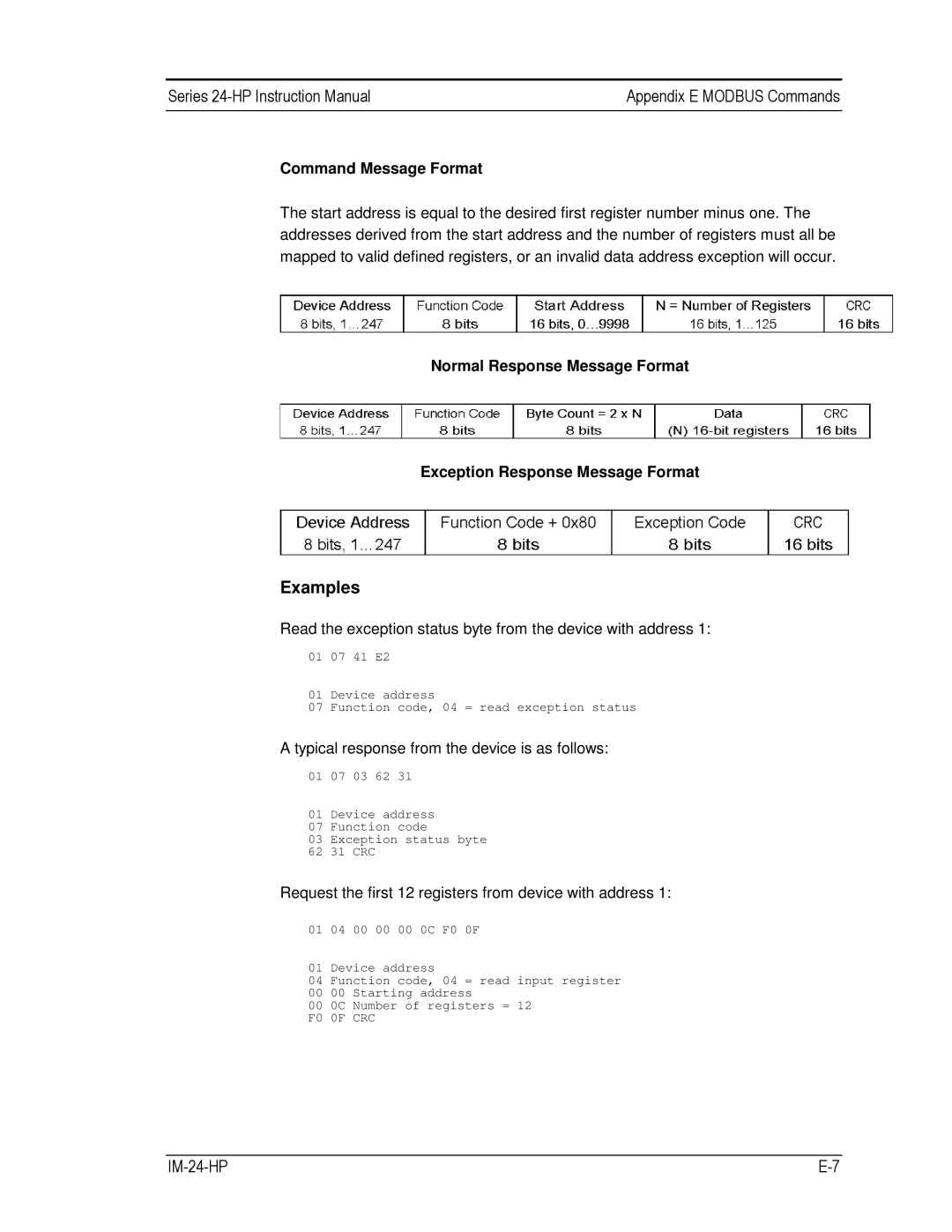
Command Message Format
The start address is equal to the desired first register number minus one. The addresses derived from the start address and the number of registers must all be mapped to valid defined registers, or an invalid data address exception will occur.
Normal Response Message Format
Exception Response Message Format
Examples
Read the exception status byte from the device with address 1:
01 07 41 E2
01 Device address
07 Function code, 04 = read exception status
A typical response from the device is as follows:
01 07 03 62 31
01 Device address
07 Function code
03 Exception status byte
62 31 CRC
Request the first 12 registers from device with address 1:
01 04 00 00 00 0C F0 0F
01 Device address
04 Function code, 04 = read input register
00 00 Starting address
00 0C Number of registers = 12
F0 0F CRC
|