Series | Appendix E MODBUS Commands |
|
|
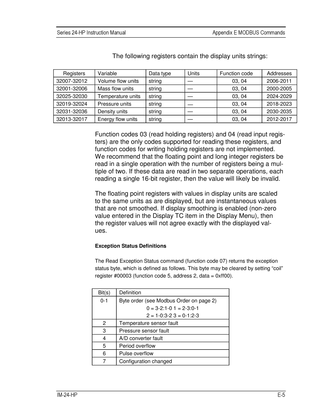
The following registers contain the display units strings:
Registers
Variable
Volume flow units Mass flow units Temperature units Pressure units
Density units Energy flow units
Data type | Units | Function code |
string | — | 03, 04 |
|
|
|
string | — | 03, 04 |
string | — | 03, 04 |
string |
| 03, 04 |
— | ||
string | — | 03, 04 |
string | — | 03, 04 |
Addresses
Function codes 03 (read holding registers) and 04 (read input regis- ters) are the only codes supported for reading these registers, and function codes for writing holding registers are not implemented. We recommend that the floating point and long integer registers be read in a single operation with the number of registers being a mul- tiple of two. If these data are read in two separate operations, each reading a single
The floating point registers with values in display units are scaled to the same units as are displayed, but are instantaneous values that are not smoothed. If display smoothing is enabled
Exception Status Definitions
The Read Exception Status command (function code 07) returns the exception status byte, which is defined as follows. This byte may be cleared by setting “coil” register #00003 (function code 5, address 2, data = 0xff00).
Bit(s) | Definition |
Byte order (see Modbus Order on page 2) | |
| 0 = |
| 2 = |
2Temperature sensor fault
3 Pressure sensor fault
4 A/D converter fault
5 Period overflow
6 Pulse overflow
7 Configuration changed
|